Advertisement
Quick Links
D2-180272-A
INSTRUCTION MANUAL
Flow Sensor
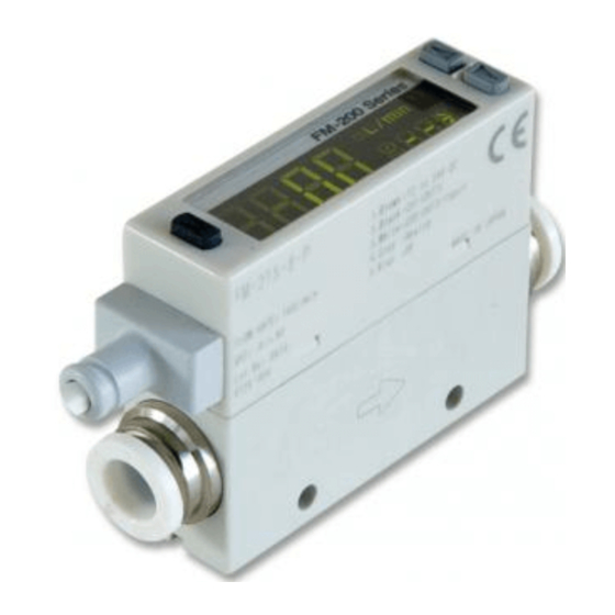
Integrated Indicator Type for Gas
FM-200 Series
Thank you very much for using SUNX products. Please read this Instruction
Manual carefully and thoroughly for the correct and optimum use of this product.
Kindly keep this manual in a convenient place for quick reference.
Never use this product in a device for personnel protection.
In case of using devices for personnel protection, use products which meet
laws and standards, such as OSHA, ANSI or IEC etc., for personnel protec-
tion applicable in each region or country.
1
PART DESCRIPTION
Main display
(Green / Red)
MODE key
Sub display (Green / Red)
Connector area for
cable with connector
Connector area
for piping
(Note 2)
one-side reverse direction, a direction opposite to the forward direction display will be the
ting
PRO MODE."
2) ø4 push-in joint / ø8 push-in joint is incorporated into FM- -4 (-P) / FM- -8 (-P), respec-
tively. The push-in joint is not incorporated into the aluminum body type.
2
PIPING
product.
Before using the product,
make sure to check that
side (upstream) of the product since the compressed air from the compressor
contains drain (water, oil oxide and foreign materials, etc.). Mesh (wire net) in the
Pneumatics
Air dryer
Filter
pressure
source
tion valve. The product may malfunction or break if subject to splattering grease or oil, etc.
dew point and ambient temperature of the product, use the product under the
conditions that dew condensations will not be formed in the inside of pipe.
In case of mounting commercial joint to the aluminum body type, apply a spanner on
the metal part of this product and tighten by the tightening torque of 16 to 18N·m.
If excessive torque is applied, the commercial joint or the main body may break.
When piping, care must be taken that foreign materials such as sealing tape
and adhesive must not enter into the inside. If the foreign materials are en-
tered, the product may malfunction or break.
Make sure to mount the joint when using the product with its secondary side (downstream)
3
WIRING
Connection method
Insert the cable with connector CN-F15-C1 (accessory) into the
connector area of this product, and mount the connector cover.
Disconnection method
Remove the connector cover and pressing the release lever of the cable with
connector, pull out the connector.
Note: Do not pull by holding the cable without pressing the release lever, as this can cause cable
break or connector break.
<Connector pin arrangement> (Sensor body)
Connector
Color code of the
pin No.
cable with connector
1
Brown
2
Black
1 2 3 4 5
3
White
4
5
Blue
Buy: www.ValinOnline.com | Phone 844-385-3099 | Email: CustomerService@valin.com
ME-FM200 No.0008-04V
Comparative output 1 indicator (Green)
Comparative output 2 indicator (Green)
UP key
DOWN key
Forward direction display
(Note 1)
Connector area
for piping
(Note 2)
Flow direction set-
Material of tube Tube diameter
Allowable diameter
Polyamid
ø4, ø8
Within ±0.1mm
ø4
Within ±0.1mm
Polyurethane
ø8
Within +0.1 / -0.15mm
Regulator
Oil mist filter
Flow sensor
(Micro-alescer)
(This product)
Connector
cover
Terminal name
+V
CH1 (comparative output 1)
CH2 (comparative output 2 / external input)
Analogue voltage output
0V
4
MOUNTING
Horizontal mounting
Use M3 screw, and the tightening torque should be 0.5N·m.
<Resin body type>
M3 screw
(Please arrange separately.)
17mm
2-ø3.4
through-hole
Vertical mounting
Use M3 screw, and the tightening torque should be 0.5N·m.
<Resin body type>
Dimension
2-M3
depth 5
M3 screw
(Please arrange separately.)
When using sensor mounting bracket
When mounting the product on the sensor mounting bracket MS-FM2-1 (op-
tional) or MS-FM2-2 (optional), use the M3 screw (length 6mm) attached to
the sensor mounting bracket. The tightening torque should be 0.5N·m.
Use M3 screw to mount the sensor mounting bracket on a sensing surface.
<Resin body type>
Use MS-FM2-1
Dimension
30
M3 screw
(Please arrange separately.)
M3 screw (length 6mm)
(Attached to MS-FM2-1)
5
I/O CIRCUIT DIAGRAMS
NPN output type
Terminal No.
(Note)
Internal circuit
PNP output type
Terminal No.
-
(Note)
Internal circuit
*1: When using CH2 as a comparative output 2
*2: When using CH2 as an external input
Non-voltage contact, NPN open-collector
transistor, or DC 2-wire output
or
High (5V or more, or Open): Invalid
Low (0.4V or less): Valid
Notes: 1) As for the aluminum body type, variable resistor (clamping voltage approx. 40V) is con-
nected between the internal power circuit and the metal body to prevent breakdown of the
that is connected to 0V. High potential and insulation resistance tests between the internal
power circuit and the metal body must not be done.
2) Short-circuit protection is not incorporated into the analogue voltage output.
Do not connect the power supply or capacitive load directly to the analogue voltage output.
Dimension
(Unit: mm)
27
<Aluminum body type>
(Unit: mm)
9.5
15.5
M3 screw
(Please arrange separately.)
<Aluminum body type>
Use MS-FM2-2
(Unit: mm)
Dimension
6
3.5
40
M3 screw
(Please arrange separately.)
M3 screw (length 6mm)
(Attached to MS-FM2-2)
Color code of cable with connector
(Brown) +V
(Black) CH1
Load
(Comparative output 1)
Load
50mA max.
(White) CH2 (Comparative output 2 / External input)
50mA max.
(Gray) Analogue voltage output
(Note 2)
(Blue) 0V
Users' circuit
Color code of cable with connector
(Brown) +V
50mA max.
(Black) CH1
50mA
(*3)
(Comparative output 1)
max.
(White) CH2 (Comparative output 2 /
Load
External input)
Load
(*1)
(Gray) Analogue voltage output
(Note 2)
(Blue) 0V
Users' circuit
*3: When using CH2 as an external input
Non-voltage contact, PNP open-collector
transistor, or DC 2-wire output
High (5V or more): Valid
Low (0.6V or less, or Open): Invalid
Dimension
(Unit: mm)
13
30
2-M3 depth 5
(Unit: mm)
30
6
3.5
(*1)
+
12 to 24V DC
±10%
-
(*2)
+
12 to 24V DC
±10%
-
or
Advertisement

Related Manuals for Sunx FM-200 Series


Summary of Contents for Sunx FM-200 Series
- Page 1 2-ø3.4 ME-FM200 No.0008-04V through-hole Thank you very much for using SUNX products. Please read this Instruction Manual carefully and thoroughly for the correct and optimum use of this product. Vertical mounting Kindly keep this manual in a convenient place for quick reference.
- Page 2 <When CH2 is set to the integration reset input function> OUTPUT MODE (RUN mode) (Integration reset input function) grated output mode, or integrated pulse output mode can be selected as the Hold down output mode for comparative output 1 and comparative output 2. Notes: 1) When CH2 is set to the teaching function, the set value cannot be checked.
- Page 3 Forcible output function Response time setting The forcible output function is used to turn ON the comparative output forc- Sets response time. The response time can be selected from seven levels: 50 ibly regardless of output mode or threshold value. The comparative output turns ON while pressing UP / DOWN key.
- Page 4 90% RH or less, Storage: 90% RH or less Enclosure: ABS Turn ON the power supply again. If not restor- Internal process error ing normally, contact SUNX. Body: Polyamide (Aluminum body type: Aluminum) Switch: EPDM, Display: Acrylic Material Mounting screw part (Resin body type): Brass limit of the display range.
Need help?
Do you have a question about the FM-200 Series and is the answer not in the manual?
Questions and answers