Table of Contents
Advertisement
Quick Links
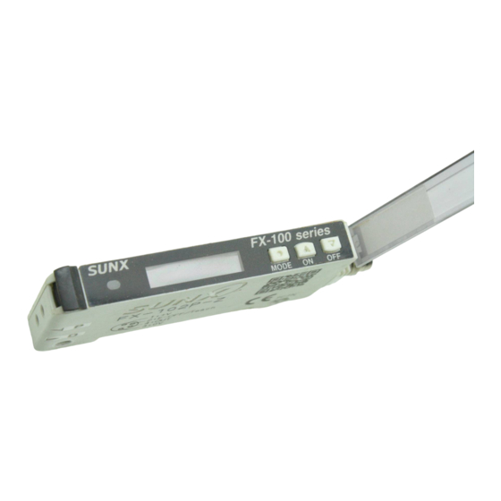
INSTRUCTION MANUAL
Photoelectric Sensor
FX-100-Z Series
Thank you very much for using SUNX products. Please read this Instruc-
tion Manual carefully and thoroughly for the correct and optimum use of this
product. Kindly keep this manual in a convenient place for quick reference.
Never use this product as a sensing device for personnel protection.
In case of using sensing devices for personnel protection, use products
which meet laws and standards, such as OSHA, ANSI or IEC etc., for
1
Operation indicator
(Orange)
Digital display (Green)
(Threshold value)
2
MOUNTING
1. Fit the rear part of the mounting section of the
2. Press down the rear part of the mounting
it.
Use M3 screws with washers for mounting.
less.
completely.
until they stop. (Note 1)
tion, till it stops.
it is inserted.
the sensing performance will deteriorate.
Digital Fiber Sensor
MJE-FX100Z No.0005-47V
WARNING
ON key /
OFF key /
Set value UP key
Set value DOWN key
MODE key
Digital display (Red)
(Incident light intensity)
ON key /
OFF key /
Set value UP key
2
35mm width DIN rail
1
2
1
Fiber lock
lever
-
or
"P" and the multi-core
and the multi-core
." If they are inserted in reverse,
" If they are inserted in reverse,
If they are inserted in reverse,
3
WIRING
connecting to this product.
Make sure to hold the side surface of this product when tightening or
nector damage.
al) into this product's connector area, and twist the
ring, pull to separate the connector.
Note: Before disconnecting, make sure to check that the
1
2
4
3
Connector pin No.
-
8V
Internal circuit
Connector pin No.
1
Internal circuit
5
When turn ON the power, the product name is displayed in the green
digital display, while the emission frequency is displayed in the red digital
display. Then switch into RUN mode [digital display (green: threshold
value, red: incident light intensity)].
M3 screw
with washer
"
" is displayed in the red digital display when emission halt is select-
3
sec. In case of lighting up the digital display again, press any key for 2
sec. or more.
2
Fiber
threshold value. (Hold down the key to make the value change faster.)
The threshold value is stored after 3 sec.
, insert the
(option-
Connector pin No.
Terminal name
1
+V
2
3
4
Output
Color code of cable with connector
(Brown) +V
(Black)
Load
Output
+
12 to 24V DC
100mA max.
±10%
–
(White) External input
*1
(Blue) 0V
Users'
circuit
Color code of cable with connector
(Brown) +V
*2
(White)
External input
+
12 to 24V DC
100mA max.
±10%
–
(Black) Output
Load
(Blue) 0V
Users'
circuit
<When turning ON the power>
<RUN mode>
Automatic
Product
Emission
Threshold
name
frequency
value
<When in RUN mode>
Threshold
Incident light
value
intensity
(optional) when
-
Cable with
connector
CN-24A-C
Fixing ring
-
Fixing ring
*1
Non-voltage contact or NPN
open-collector transistor
or
Open): Invalid
*2
Non-voltage contact or PNP
open-collector transistor
or
-
Open): Invalid
Incident light
intensity
"
."
Advertisement
Table of Contents

Related Manuals for Sunx FX-100-Z Series


Summary of Contents for Sunx FX-100-Z Series
- Page 1 Digital Fiber Sensor FX-100-Z Series nector damage. MJE-FX100Z No.0005-47V Cable with Thank you very much for using SUNX products. Please read this Instruc- connector tion Manual carefully and thoroughly for the correct and optimum use of this CN-24A-C (option- product. Kindly keep this manual in a convenient place for quick reference.
- Page 2 The key lock function prevents key operations so that the conditions set in each setting mode are not inadvertently changed. the use environment when teaching. In the key lock condition, “ ” is displayed when any key is pressed. [Key lock set] <When in RUN mode>...
- Page 3 Setting item Factory setting Shift setting mode light intensity as a threshold value. setting mode +, limit -, AUTO, and ECO. <RUN mode> Threshold value mode can change the threshold value with each set cycle de- follow-up cycle pending on variations of the incident light intensity. The follow- Press for 4 sec.
- Page 4 ” come with CE When “–” is selected, the set content of the digit is not changed. Marking. .” SUNX Limited URL : sunx.jp In case of errors, attempt the following measures. Overseas Sales Dept. (Head Office) Error description Measures...
Need help?
Do you have a question about the FX-100-Z Series and is the answer not in the manual?
Questions and answers