
Subscribe to Our Youtube Channel
Related Manuals for Et system ELP/DCH Series


Summary of Contents for Et system ELP/DCH Series
- Page 1 User’s Manual ELP/DCH series PROGRAMMABLE DC ELECTRONIC LOAD ET System electronic GmbH 2021-06-10 Manual Edition V.2.2...
-
Page 2: Table Of Contents
ET System electronic GmbH Content Contents Introduction ............................4 Chapter 1 Size and Installation ........................... 8 1 .1 Dimension .............................. 8 1.2 Installation ............................. 10 1.3 Plug in Power Cord ..........................10 Chapter 2 Quick Start ............................11 2.1 Product Introduction ..........................11 2.2 Features .............................. - Page 3 ET System electronic GmbH 8.2 DB9 ............................... 77 8.3 Protocol ..............................78 8.4 SCPI Communication Instruction ......................79...
-
Page 4: Contents Introduction
Contents Introduction Thank you for purchasing ELP/DCH series DC Electronic Load. To obtain maximum performance from the product, please read this manual first, and keep it handy for future reference. We will use the alias E-load of DC Electronic Load in the following. - Page 5 ET System electronic GmbH Indicates very important message in this manual. When the symbol is printed on the instrument, refer to a corresponding topic in the Instruction Manual. Indicates DC (direct current) Indicates a fuse Indicates earth terminal In this manual, the risk seriousness and the hazard levels are classified as follows.
- Page 6 ET System electronic GmbH Near induction heating systems (such as high-frequency induction heating systems and IH cooking equipment) Susceptible to vibration Checking before use Before using the instrument at the first time, verify that it operates normally to ensure that no damage occurred during storage or shipping.
- Page 7 ET System electronic GmbH Be sure to connect the test lead correctly. Wear gloves of rubber or similar materials during measurement. For achieving the measurement accuracy, it is recommended that the equipment should be operated half an hour after power-on.
-
Page 8: Chapter 1 Size And Installation
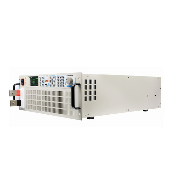
ET System electronic GmbH Chapter 1 Size and Installation 1 .1 Dimension ELP/DCH series electronic load dimension Figure 1.1 Appearance of instrument... - Page 9 ET System electronic GmbH Figure 1.2 Instrument dimension 1 Figure 1.3 Instrument dimension 2...
-
Page 10: Installation
ET System electronic GmbH 1.2 Installation This instrument is intended for indoor use in a pollution degree 2 environment. Please refer to the specifications table for the allowable environment operating limits. Figure 1.6 E-Load outline diagram (unit mm) There are 2 cabinet mounting holes on the both sides of the E-load. After removing the gap, it can be used for cabinet installation and positioning. -
Page 11: Chapter 2 Quick Start
ET System electronic GmbH Chapter 2 Quick Start This chapter describes the power-on check procedure for the ELP/DCH Series load to ensure that the E-load is properly started and used during initialization. It also introduces the E-load front panel, rear panel, keyboard button functions and LCD display function to ensure that you can quickly understand the appearance, structure and button usage of the E-load before operating the E-load. - Page 12 ET System electronic GmbH simulate a variety states of load change. OCP mode Over current protection point test mode. EFFECT mode Load effect test mode. AUTO mode 5) Actual LED simulation to test LED power. 6) Voltage/current ripple test (Vpp, Ipp );...
-
Page 13: Front Panel
ET System electronic GmbH 18) Power-off to maintain memory function; 19) USB port upgrade procedure; 20) Electrically isolated communication for I/O interface, RS232/485, NET network port; 2.3 Front Panel The following picture is the front panel for the ELP/DCH E-Load. All models have the same front panel, only the terminal section will vary based on the model. -
Page 14: Lcd Status Bar Function
11 digital keys and is backspace key 2.4 LCD Status Bar Function The following screen is ELP/DCH series E-oad LCD display interface.The status bar is the top line icons. There are several icons on the status bar in the top line. - Page 15 ET System electronic GmbH Figure 2.2 LCD interface Item Description Instrument operating mode and status bar (described in the below table); Readback value display Present loading value edit box E-load protection limit setting E-load conversion parameter value display Status bar icon description The remote compensation function is turned on.
-
Page 16: Rear Panel
ET System electronic GmbH means E-load connecting to the PC, it is allowed to Send commands on the PC to perform related operations on the E-load. 2.5 Rear Panel The following picture is the rear panel for the ELP/DCH E-load. -
Page 17: Self-Test Process
ET System electronic GmbH can be used by the user normally. Before operating the E-load, make sure you understand the safety instructions. Ensure that the line voltage selector switch on the back panel is set to match your line voltage. Failure to do so could result in damage to the instrument. - Page 18 ET System electronic GmbH problem. 1. Make sure the power cord is connected properly and the power switch has been pushed in to ON. Go to step 2 ---- when the power cord is well connected Back to step 1----- when the power cord is wrongly connected 2.
-
Page 19: Chapter 3 Functions And Features
ET System electronic GmbH Chapter 3 Functions and Features This chapter will introduce functions and features of ELP/DCH E-load in the following sections: Basic operation modes LIST function OCP over current test function EFFT load effect test function ... -
Page 20: Constant Current Mode (Cc)
ET System electronic GmbH 3.1.1 Constant Current Mode (CC) In constant current mode, the DC E-load will sink a constant current, regardless of the voltage of the source. See the figure below. Figure 3.1 CC mode In CC mode, the E-load provides two methods to set the constant current value. -
Page 21: Constant Voltage Mode (Cv)
ET System electronic GmbH 3.1.2 Constant Voltage Mode (CV) In constant voltage mode, the E-load will cause a constant voltage to appear at its terminals. Figure 3.2 CV mode In CV mode, the E- load provides two methods to modify the constant voltage value. -
Page 22: Constant Resistance Mode (Cr)
ET System electronic GmbH 3.1.3 Constant Resistance Mode (CR) In constant resistance mode, the E-load will behave as a fixed resistance value. As shown in the figure below, the E-load changes the current linearly as the input voltage changes. Figure 3.3 CR mode In CR mode, the E-load provides two methods to set the constant resistance value. -
Page 23: Constant Power Mode (Cw)
ET System electronic GmbH 3.1.4 Constant Power Mode (CW) In CW mode, the E-load will cause a constant power to be dissipated in the load. As shown in the figure below, if the input voltage rises, the input current will decrease and the power P(=V * I) will remain constant at the level of setup power. -
Page 24: List Operation
ET System electronic GmbH 3.2 List Operation With LIST mode, E-load can loading an accurate, fast and complicated current, which can be synchronized by internal or external signals to complete multiple quasi-bit load precision tests. Figure 3.5 LIST mode test interface Edit the LIST file and trigger to operate this file. - Page 25 ET System electronic GmbH Figure 3.6 Edit the LIST file LIST parameter setting Parameter Description Curr Loading current Time Duration, setting range 10uS ~ 50S Rate Current slew rate 0.001-3A/uS List mode setting: List test interface→SET CONT Continuous mode--sequential loading mode Counting mode-- when it receives a trigger signal, the load will start List operation for CNT cycles till completion.
- Page 26 ET System electronic GmbH Users can edit up to 8 sets of list files. If the E-load operation mode is List operation, the E-load will start a List operation when the key ON/OFF is pressed till completion or the ON/OFF is pressed again to stop the loading.
-
Page 27: Ocp Test Function
The test waveform is shown in Figure 3.7. 3.3 OCP Test Function The ELP/DCH series E-load is provided with over-current protection test function (OCP). Under OCP test mode, when the voltage of source under test reached Von value, delay for a while for the E-load to latch. - Page 28 ET System electronic GmbH Figure 3.10 OCP parameter setting interface OCP parameter OCP parameter: Istart Start Current Iend End Current Step Steps(1~1000) Dwell Step duration(0.01~999.99) V trig Trigger voltage level Ocp Lo Lower limit of over-current Ocp Hi Upper limit of over-current...
-
Page 29: Efft Function
ET System electronic GmbH 3. The E-load starts loading from 3A and stops at 6A in 100 steps with a step value 0.03A. The delay of each step is 0.01S. When the power supply voltage is less than the 1V trigger voltage, the corresponding current value is the OCP current value, and it is judged whether the OCP current value is within the upper and lower limits of the current. -
Page 30: Auto Test Function
ET System electronic GmbH EFFT setting parameter Parameter Description Imin Draw minimum working current Imax Draw maximum working current Inor Draw normal working current Delay Current duration per step For example: Source under test: constant voltage source 24V, output current 0-5A, normal working current 3A. - Page 31 ET System electronic GmbH (Mode), and the detection types (SPEC) supported by different working modes are also different. See the following table for details. The load parameters in each mode are also different. See the corresponding chapters of each mode. Introduction.
- Page 32 ET System electronic GmbH Choose the appropriate current range according to the real test I-range condition Step No. Select the specified step for parameter setting Mode Description Empty CC mode CV mode CW mode CR mode SHORT Short EFFT EFFECT LED driver source test mode Comparison type setting: AUTO parameter editing interface →...
- Page 33 ET System electronic GmbH Test delay Time from start loading to read the test value Unloading wait time for completing a single step test (Figure 3.14) time Trigger output and test process setting: test page → press MENU → system setting →...
- Page 34 ET System electronic GmbH current 3A. Purposes: to test comprehensive performance of power supply 1. Load capacity test: 3A normal current, to compare voltage within range of 23.5~24.5V. 2. Over-current protection test: use OCP mode to test if the power supply over-current point within the range of 4.8~5.2A.
-
Page 35: Dynamic Function
ET System electronic GmbH Stop testing the next steps when one step fails. 17. After the above settings are completed, press return test interface. Press start the test. Because start voltage is set to 5V, in the future, when the E-load detects an input voltage greater than 5V, the E-load will automatically start to test.( If start voltage set... - Page 36 ET System electronic GmbH Figure 3.16 DYNA testing page Figure 3.17 DYNA Setting Page DYNA mode setting In continuous mode, the E-load can load between high and Conti low current in different rise rates and duration.
- Page 37 ET System electronic GmbH In pulse-mode, with dynamic test operation enabled, the load will switch to Ib every time after receipt of a trigger Pulse signal and switch back to Ia value after maintaining Tb for pulse width time. In toggle mode, the load current will drop to Ia according to...
- Page 38 ET System electronic GmbH every time after receipt of a trigger signal and switch back to Ta value after maintaining Tb for pulse width time. Figure 3.19 DYNA- pulse mode TRIGGER mode In toggle mode, after enabling dynamic test operation, the load will be switched continuously between Ia value and Ib value after receipt of every trigger signal.
-
Page 39: Battery Test Function
ET System electronic GmbH Object under test: constant voltage source 24V, output current 0-5A, normal working current 3A. Purposes: to test power supply dynamics characteristic, Vp+, Vp- Operation steps: Press the key to enter the mode selection page, press the up and down keys to... - Page 40 ET System electronic GmbH Figure 3.22 Battery mode setting page BATT Setting parameters Parameters Description Mode Discharge mode CC/CW/CR Value Load value in different discharge modes Stop Time Discharge stop time (termination conditions) Unit AH/WH Stop Volt Discharge stop voltage (termination conditions)
-
Page 41: Short-Circuit Simulation Function
ET System electronic GmbH Operation steps: 1. Press the key to enter the mode selection page, press the up and down keys to select BATT, and press the key to enter the BATT test interface, as shown in Figure 3.21. -
Page 42: Led Simulation Function
ET System electronic GmbH Figure 3.23 Short-circuit mode test Page 3.9 LED Simulation Function The E-load can simulate the LED at the input, press the key on the E-load front panel to select the LED function to switch the LED working state. The LED equivalent circuit is as follows: Figure 3.24 LED I-V curve... - Page 43 ET System electronic GmbH measured LED driver Rd --- Resistance of LED driver, can be calculated by V-I curve Rd Coefficient = Rd / (Vo / Io) Vf——LED Positive conduction bias, can be calculated from the Rd, please find the specific example as follows.
- Page 44 ET System electronic GmbH LED setting parameters Parameters Description Led Vo Voltage of operating point Led Io Current of operating point Led Rf Coefficient Coeff Io is given by LED Driver, if there is an error between the actual output and the set value, the corresponding load value Vo will be different.
- Page 45 ET System electronic GmbH range. Regardless of the number of LED in series, the operating point resistance Rd is equal to Coeff (Coeff<1) multiplied by the value of Vo/Io. Therefore, the user can get Io from the rated output current of LED driver and calculate the RdCoeff parameter according to I-V curve on LED specification.
-
Page 46: Sweep Dynamic Frequency Conversion Scanning
ET System electronic GmbH 3.52−3.35 so a single LED Rd = Rd= =1.7 Ω 0.4−0.3 0.35 From formula 3.3, Rf= Rd× =1.7× =0.173 3.44 4. After the setting is completed, press the key to back to the test interface, press the to start testing. - Page 47 ET System electronic GmbH Figure 3.28 SWEEP function testing page Figure 3.29 SWEEP function setting Page SWEEP setting parameters Parameter Description Low current(Imin) Low level load current High current(Imax) High level load current Starting frequency(Fstart) Initial scan frequency, 0.01Hz~50KHz Cut-off frequency (Fend)...
-
Page 48: Timing Time Measurement
ET System electronic GmbH Rate of decline Current drop rate 0~3 Auto: auto-execute by setting Manual: Press the up and down keys to adjust Operating mode(mode) the frequency, step frequency is Fstep Test case: constant voltage source is 24V, output current is 0-5A, normal working current is 3A. - Page 49 ET System electronic GmbH Figure 3.30 TIMING mode test Page Figure 3.31 TIMING mode setting interface TIMING function parameter table: TIMING parameter settings Parameter Description CC/CV/CP/CR/OFF available Load mode(Load mode) Set the load value of current, voltage, etc. Load Value(Load Val)...
-
Page 50: Dcr Dc Resistance Measurement Function
ET System electronic GmbH Ending trigger setting(TRIG.END) VOLT/CURR/EXT(External trigger) Trigger signal(Signal) Trigger mode(Edge) rise(RISE)/fall(FALL) When the voltage, current, etc. trigger setting Trigger value(level) value is started, the timing starts. For example: constant voltage source is 24V, output current is 0-5A, normal working current is Test purpose: Power climb time, the time of the power climbing from 2.4V to 21.6V. - Page 51 ET System electronic GmbH As shown above, connect the battery to be tested, turn on the remote compensation function, and then go to the test page. Set the steps as follows: 1. Press to enter the mode selection page, press up and down key selection DCR, press key to enter the DCR test interface figure 3.32.
-
Page 52: Measurement Item
ET System electronic GmbH 3.33. Figure 3.33 DCR Mode Setup Interface 3. Set test parameters. DCR Setting Parameters Parameters Note Imin Battery minimum discharge current Imax Maximum discharge current of battery V Io Lower limit for voltage comparison V hi... -
Page 53: Ripple Measurement
ET System electronic GmbH 3.13.2 Ripple measurement The E-load can test voltage ripple (Vpp), current ripple (Ipp) and display in real-time. The measurement method is different from the traditional measurement of oscilloscope with blocking capacitance. The E-load ripple measurement within the measurement bandwidth behave a good flat, so the ripple measurement is more accurate and has extremely high repeatability. -
Page 54: Chapter 4 System Settings And Save Function
ET System electronic GmbH Chapter 4 System settings and Save function Press key to go to system configuration and save f interface, as shown below: Figure 4.1 MENU Page The system settings is used to set the parameters of the load, such as range, protection, Von, Voff, etc. -
Page 55: Von/Voff Function
ET System electronic GmbH System Setting(SYSTEM) V-Range low voltage range 0~15.2V HIGH high voltage range 0~152V I-Range low current range 0~3.2A HIGH high current range 0~32A I-Prot Exceed the set value of 0.0002~32A, load protection P-Prot Exceed the set value of 0.001~155W, load protection Set 0V means the function is off. -
Page 56: Source Type Selection Function
ET System electronic GmbH Figure 4.3 Von、Voff If Von-Delay parameter is set, the E-load will load, when the source voltage reached Von and have delayed for Von-Delay time. 4.1.2 Source Type Selection Function The E-load has the function of automatically detecting the type of source under test. But in some special cases, the source loaded dosen’t meet your expectations. - Page 57 ET System electronic GmbH Figure 4.4 Configuration Page Configuration setting MEASURE SET Fast Real-time display and loading test Rate Display and loading test after multiple Slow sampling Remote sense function OFF Remote sense Remote sense function ON Key sound function OFF...
-
Page 58: Remote Sense Compensation Mode
ET System electronic GmbH Address Address range from 1~99 ON: One interface and address bit controls multiple E-loads Multi loads communication OFF: Multiple interfaces control multiple E-loads OUTPUT LEVEL- high level as default, low level when there is an output... -
Page 59: Shortcut Call Mode
ET System electronic GmbH Figure 4.5 Remote Sense Setting Page Remote measurement access, please refer to the figure as below. Wiring Diagram of Remote Sense: Figure 4.6 Remote-Sense wiring Diagram If the remote compensation started, the wiring must be the same as above, otherwise the voltage detection function will be fail. -
Page 60: Trigger Output Settings
ET System electronic GmbH If the Shortcut Call is enabled, the digital 0~9 keys will change the original function, only the calling function is retained, and the display status bar will display SHORTCUT. When Shortcut Call is turned off, the numeric keys will return to normal. - Page 61 ET System electronic GmbH Press the key SAVE to save above settings to the file 1 where the cursor is located, and rename it as needed. If you need to call a saved test file, there are two ways: 1. Press the key to go to the setting page and select Save, then select the desired file and press the key Loading to call the stored test mode.
-
Page 62: Chapter 5 Protection Function
ET System electronic GmbH Chapter 5 Protection Function The E-load is provided with following protective functions: 1. overvoltage protection (OVP), 2. over-current protection (OCP), 3. over-power protection (OPP), 4. over-temperature protection (OTP) 5. input v0oltage reverse protection (RV) If any one of the above protections is enabled, the E-load will have corresponding actions. -
Page 63: Over-Power Protection (Ovp)
ET System electronic GmbH Figure 5.2 OCP Page 5.3 Over-power protection (OVP) The E-load provides over-power protection. When the input power is higher than the setting power (See Chapter 4.1 - System Settings - Power Protection), the E-load will display” OVER POW”, the E-load will be immediately OFF and the buzzer will sound. -
Page 64: Input Voltage Reverse Protection (Rv)
ET System electronic GmbH automatically be OFF and the buzzer will sound. Press any key to cancel the beeper. Figure 5.4 OTP Page 5.5 Input Voltage Reverse Protection (RV) When the polarity of the input voltage is reversed, the E-load will display” REVERSE”, the E-load will be immediately OFF and the buzzer will sound. -
Page 65: Chapter 6 I/O Interface
ET System electronic GmbH Chapter 6 I/O Interface The E-load provides I/O interface, which is convenient for the user to connect the external control signal output and other control units to complete the automatic test. 6.1 I/O Interface Figure 6.1:I/O interface... - Page 66 ET System electronic GmbH 1. The EXV port is an external power supply input port. It can be accessed when the user-specified voltage is required. When the external voltage is not connected, the internal isolation E5V is supplied. 2. GND is the isolated power ground.
-
Page 67: Chapter 7 Specifications
ET System electronic GmbH Chapter 7 Specifications We use FS (full scale) to define measurement tolerances. FS: Maximum display value or measurement range. 7.1 Main Specifications ELP/DCH8402B ELP/DCH8402C ELP/DCH8402 Model Input voltage 150V 500V 150V 240A 120A 500A Input current... - Page 68 ET System electronic GmbH Accuracy ± (0.025%+0.025%FS) Read-back current Range 240A 120A 500A Resolution 0.1mA 0.09mA 0.9mA 0.3mA Accuracy ± (0.05%+0.05%FS) Read-back Ripple 150V/240A Range(R/I) 500V/120A 150V/500A 10Hz~250kHz bandwidth Accuracy ±1% Protection range Overpower 4200W protection Overcurrent 252A 126A 525A...
- Page 69 ET System electronic GmbH Accuracy ±0.1% CW mode Range 5000W Resolution 16Bits Accuracy ±(0.2%+0.2%FS) Dynamic mode 10us~50s Ta&Tb Minimum 10us resolution Maximum 2.5A/us 1A/us 5A/us up/down slope Read-back voltage Range 150V 500V 150V Resolution 0.1mV 0.3mV 0.1mV Accuracy ± (0.025%+0.025%FS)
- Page 70 ET System electronic GmbH Mini. rise time at 100us 100us 100us full-scale current CV mode Range 150V 500V 150V Resolution 0.2mV 0.7mV 0.2mV Accuracy ± (0.025%+0.05%FS) CC mode Range 240A 120A 500A Resolution 0.3mA 0.1mA 0.7mA Accuracy ± (0.1%+0.1%FS) CR mode Range 0.1Ω~7.5kΩ...
- Page 71 ET System electronic GmbH Over-temperature ≒85℃ protection Specification Size (length 624mm*483mm*177mm width * height) 50kg Weight(Kg) ELP/DCH8802 ELP/DCH8802B ELP/DCH8802C Model Input voltage 150V 500V 150V 240A 120A 500A Input current Input power 8000W Mini. operating 1.5V@240A 2V@120A 1.5V@500A voltage Mini. rise time at...
- Page 72 ET System electronic GmbH Range 240A 120A 500A Resolution 0.1mA 0.09mA 0.9mA 0.3mA Accuracy ± (0.05%+0.05%FS) Read-back Ripple 150V/240A 500V/120A 150V/500A Range(R/I) 10Hz~250kHz bandwidth Accuracy ±1% Protection range Overpower 8400W protection Overcurrent 252A 126A 525A protection Overvoltage 158V 525V 158V...
- Page 73 ET System electronic GmbH Range 10kW 12kW Resolution 16Bits Accuracy ±(0.2%+0.25%FS) Dynamic mode 10us~50s Ta&Tb Minimum 10us resolution Maximum 2.5A/us 5A/us 2.5A/us 5A/us up/down slope Read-back voltage Range 500V 500V 500V 150V Resolution 0.3mV 0.1mV 0.3mV 0.1mV Accuracy ±(0.025%+0.025%FS) Read-back current...
- Page 74 ET System electronic GmbH CV mode Range 500V 150V 500V 150V Resolution 0.7mV 0.2mV 0.7mV 0.2mV Accuracy ±(0.05%+0.05%FS) CC mode Range 240A 500A 240A 500A Resolution 0.3mA 0.7mA 0.3mA 0.7mA Accuracy ±(0.1%+0.1%FS) CR mode Range 0.1Ω~7.5kΩ 0.1Ω~7.5kΩ 0.1Ω~7.5kΩ 0.1Ω~7.5kΩ Resolution...
- Page 75 ET System electronic GmbH Specification Size (length 624mm*483mm*12U width * height) Weight(Kg) 145Kg 155Kg ELP/DCH8183B ELP/DCH8183C ELP/DCH8203B ELP/DCH8203C Model Input voltage 500V 150V 500V 150V 240A 500A 240A 500A Input current Input power 18kW 20kW Mini. operating 2V@240A 1.5V@500A 2.5V@240A 1.5V@500A...
- Page 76 ET System electronic GmbH Read-back Ripple 500V/240A 150V/500A 500V/240A 150V/500A Range(R/I) 10Hz~250kHz bandwidth Accuracy ±1% Protection range Overpower 18900W 21000W protection Overcurrent 252A 525A 252A 525A protection Overvoltage 525V 158V 525V 158V protection Over-temperature ≒85℃ protection Specification Size (length 624mm*483mm*12U...
-
Page 77: Chapter 8 Communication Interfaces
This chapter mainly introduces the communication mode, method, and protocol of the ELP/DCH series E-load. 8.1 Communication module ELP/DCH series E-load is provided with three communication interfaces to communicate with a computer for selection, including RS232, RS485 and LAN. i. Press any key on any work interface to enter the parameter setting interface;... - Page 78 ⑥.NC ⑦.NC ⑧.485A ⑨.485B 8.3 Protocol The ELP/DCH series of E-loads supports SCPI protocol. Its data frame structure consists of four parts: Set the additional address (to be set only when multi-machine communication is on) i. Press the key on any working interface to enter the parameter setting interface;...
- Page 79 ET System electronic GmbH Iii. Select the baud rate you want. At present, the E-load only supports 9600, 19200, 38400 and 57600. 8.4 SCPI Communication Instruction *IDN? Meaning: Query version number Return:8151, V1.0 Example: query version number Send: *IDN? Back: 8151,V1.0...
- Page 80 ET System electronic GmbH Meaning: set current rise time Example: set current rise time 3A/uS Send: CURRent: SLEW: RISE 3 Back: no CURRent:SLEW:FALL Meaning: set current fall time Example: set current fall time 3A/uS Send: CURRent: SLEW: RISE 3 Back: no...
- Page 81 ET System electronic GmbH RESistance CR mode DYNamic Dynamic mode LED mode OCP mode LIST LIST mode SHORT SHORT mode SWEEP SWEEP mode TIMing TIMing function AUTO AUTO mode EFFT EFFT mode 14 CURRent Meaning: set the current value in CC mode...
- Page 82 ET System electronic GmbH Send: MEASure: CURRent? Returns: 00.0000 20 MEASure:POWer? Meaning: read measured power value Example: read measured power value Send: MEASure: POWer? Returns: 00.000 21 MEASure:RESistance? Meaning: read measured resistance value Example: read measured resistance value Send: MEASure: RESistance? Returns: 00.0000...
- Page 83 ET System electronic GmbH Returns: 00.0000 27 POWer:PROTection? Meaning: read the power protection value Example: read the power protection value Send: POWer:PROTection? Returns: 00.0000 28 DYNamic:HIGH Meaning: set high level loading current in dynamic mode Example: set high level loading current at 3A in dynamic mode...
Need help?
Do you have a question about the ELP/DCH Series and is the answer not in the manual?
Questions and answers