
Related Manuals for Et system LAB-HP/E Series


Summary of Contents for Et system LAB-HP/E Series
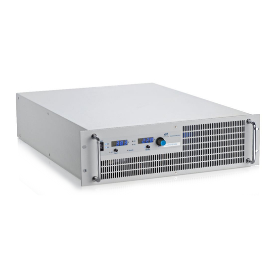
- Page 1 LAB - H P/ E ET System electronic GmbH Telefon 06205 3948-0 Fax 06205 37560 Hauptstraße 119-121 info@et-system.de 68804 Altlußheim www.et-system.de...
- Page 2 Software version: V15 November 2016...
-
Page 3: Table Of Contents
Table of Contents Info & Contact Addresses ............................1 Technical Specifications .............................. 2 Input Specifications ................................ 2 Output Specifications ..............................3 AI Interface ..................................4 RS 232 ..................................... 4 RS 485 ..................................... 4 EMC and Safety standards ............................. 4 Ambient Conditions ................................ 4 Important Safety Instructions ............................. - Page 4 Digital Input ................................. 25 Activation (Ext. Control) ............................25 Blocking (Standby) ..............................25 Digital Output ................................25 Blocking (Standby) ..............................25 Const. Voltage mode (CV) ............................25 Error ..................................... 25 Ext. Control: Ethernet (LAN) ............................26 Determinating the IP using the Device Installer by LANTRONIX ................. 26 Controlling the device via Telnet ..........................
-
Page 7: Info & Contact Addresses
INFO & CONTACT ADDRESSES ET System electronic GmbH was founded in 1986 in the heart of the Rhine-Neckar-Triangle. As a subsidiary of a leading electricity utility group, the company quickly took on a leading role in the area of laboratory power electronics and associated electrical measurement. -
Page 8: Technical Specifications
11 The ripple measurment methode of ET-System is specified at application note „ET Ripple-Spec. (Page 32) 12 The ripple specification is reservation to change on the part of manufacturer 13 Device is at the moment only available with highspeed output (Low output cap.) 14 Not as standard Unit available ET System electronic GmbH... -
Page 9: Output Specifications
The output current can not go over the set value Over Temperature Protection: if the internal heat sink tempearatury is go above 90°C the divice will automaticaly shut down Voltage and Current operation mode: Voltage and current are setable UI-Modus ET System electronic GmbH... -
Page 10: Ai Interface
IMPORTANT SAFETY INSTRUCTIONS ET System electronic GmbH... -
Page 11: Important Safety Instructions
This operating manual is based on the state of technology at the time of printing. However, it is possible that despite regular control and correction, the present document contains printing errors or deficiencies. ET System electronic GmbH assumes no liability for any technical, printing or translational errors within this manual. -
Page 12: Drawing
Important Safety Instructions ET System electronic GmbH... -
Page 13: Functional Description
Important Safety Instructions FUNCTIONAL DESCRIPTION HE FOLLOWING BLOCK DIAGRAM GIVES INFORMATION ABOUT THE VARIOUS ADJUSTMENT OPTIONS UI-Mode Unit is oprated with current and voltage limitation. ET System electronic GmbH... -
Page 14: General Settings
Since the device is operated in UI mode only, the set values for voltage and current will be transferred directly to the switching regulator. There is no additional digital control. The following picture displays the control panel and control structure of the device. ET System electronic GmbH... -
Page 15: Voltage Settings
This feature adjusts the voltage levels of analog input signals and analog output signals. Selectable ranges are 0-5 V and 0-10 V. ESCRIPTION OF THE DIFFERENT Constant Voltage Preset Voltage Constant Current Preset Current Over Voltage Protection Remote Local or Remote Operation Standby Standby Status ET System electronic GmbH... -
Page 16: Universal Interface
Example: Adjustment of output voltage 10 V/5 A (full command sequence) OVP,100 adjusts OVP to 100 V adjusts output voltage to 10 V UA,10 current limiting 5 A IA,5 output enabled SB,R ET System electronic GmbH... -
Page 17: Instruction Set
This command deletes the status byte. It affects only the status byte of the interface, the command was sent from. No return value. For detailed description of the status byte see the different interface chapters. DCL - Device Clear This command resets the initialization data. No return value. Caution: Interface parameters are also reset! ET System electronic GmbH... - Page 18 ID or IDN? - Identification This command displays the identification string. Return value: <ID-String>. LLO - Local Lockout Local Standby This command deactivates the button. Unit cannot be switched to local mode by holding the button No return value. ET System electronic GmbH...
- Page 19 This command shows the measurement value of the present output voltage. Example:LAB/HP/E 15100 (100VDC; 150A) Remote operation mode OVP,140 Over voltage protection 140 V UA,10 Output voltage 10 V IA,1 Output current 1 A SB,R Output open Measures present output voltage MU,10.0V Unit answers: 10,0 V ET System electronic GmbH...
- Page 20 Allowed parameters for RS232 interface: PCx,<baud>,<parity>,<data bits>,<stop bits>,<handshake>,<echo> Parameter Function Baud: 1200, 2400, 4800, 9600, 14400, 19200, 38400, 57600, 62500, 115200 Parity: O, E, N Data bits: 7, 8 Stop bits 1, 2 Handshake: H, S, N Echo: E, N ET System electronic GmbH...
- Page 21 Example: Remote operation mode OVP,200 Over voltage protection 200 V UA,100 Output voltage 100 V IA,10 Output current 10 A SB,R Output is active Retrieve standby status SB,R Unit answers: output is active ET System electronic GmbH...
- Page 22 Output voltage 250 V. Since the output voltage was limited to 200 V via configuration menu, voltage limitation is adjusted to 200 V. An error bit is not set. Query of adjusted voltage UA,200.0V Unit answers: set point U = 200,0 V ET System electronic GmbH...
-
Page 23: Response String
UA at a 600 V unit UA,123.0V UA at a 50 V unit UA,23.44V The digits before the decimal point depend on the present measurement value. Example: 600 V unit UA,10.0V UA,220.0V UA,1.0V Example: 50 V unit UA,1.23V UA,10.47V UA,0.01V ET System electronic GmbH... -
Page 24: Ext. Control: Computer
SGND Signal Ground Table: Device address Address Address The device address is read in only when the unit is switched on. Changing the DIP switches while the unit is active will not change the device address! ET System electronic GmbH... -
Page 25: Status Word
The ESR register can be read using the command . Return value: ESR,xxxxxxxx. After the query, the ESR register is deleted. Function Power on Command error User request Execution error Device dependent error Query error Request control Operation complete ET System electronic GmbH... -
Page 26: Rs232 Interface
Parity mode (1 = odd, 0 = even) Stop bit (1 = 2 stop bits; 0 = 1 stop bit) Data format (1 = 8 bit; 0 = 7 bit) used internally, can be 1 or 0 Table Table Table ET System electronic GmbH... -
Page 27: Interface Reconfiguration
‘#’ before it. When using the word ‚ALL‘ instead of a number, the following command will be executed by all connected devices (e. g. #1,ID; #22,GTR, #ALL,GTL). ET System electronic GmbH... -
Page 28: Interface Reconfiguration
In case, the user has forgotten the active setup, there are two ways of reconfiguring the interface: <PCx> sending the command from one of the other interfaces using the display to configure the interface Interface Parameters ET System electronic GmbH... -
Page 29: Ext. Control: Ai Interface
Signals shut down by OVP -nc- All digital outputs are OC outputs with a pull-up resistance after + 5 V. All analog inputs and outputs can be operated in 0-5 V or in 0-10 V mode. ET System electronic GmbH... -
Page 30: Analog Input
Present set point of the preset output current. Measurement value refers to the rated current of the device. Example: LAB/HP/E at 100 A output current, AI adjusted to 10 V, voltage at output I = 2 V. Present set point: I = 2 V 100 V ÷ 10 V = 20 A ET System electronic GmbH... -
Page 31: Istmon Real Value)
Constant voltage mode is set, when the unit is in constant voltage mode. RROR An error is set, if the unit has been shut down by OVP. To reset this error, the standby mode must be activated. ET System electronic GmbH... -
Page 32: Ext. Control: Ethernet (Lan)
Search, all XPORTS within the network are displayed. The current assigned (dynamical) IP will also be displayed. This IP can be entered in the address line of a browser. If you want to set a static IP Adress use “Assign IP”. ET System electronic GmbH... -
Page 33: Controlling The Device Via Telnet
The IP address must be entered within the tab Port in the following format: xxx.xxx.xxx.xxx:10001. Afterwards the button Open must be clicked. In the terminal box the desired commands can be sent to the device. For more Information please look at: http://www.et-system.de/en/produkte/applications-special-units.html ET System electronic GmbH... -
Page 34: Ext. Control: Usb
In case, the user has forgotten the active setup, there are two ways of reconfiguring the interface: <PCx> sending the command from one of the other interfaces using the display to configure the interface Interface Parameters ET System electronic GmbH... -
Page 35: Sense Mode
1-10 µF capacitor should be connected to the output. If thus you paid attention to the points stated above, oscillation occurs through load or power induction and complex load situations, please contact our company ET System. ISTRIBUTION WITHOUT... -
Page 36: General Information For Sensing
The circuit breaker (S_power) must be closed when starting before the Sens (S_sens). When switching off, the Sens must first be opened and then the circuit breaker can be opened. Otherwise, a current flow may occur across the sensing line, and this may be particularly critical when disconnecting. ET System electronic GmbH... -
Page 37: Appendix
Example illustration from the norm protective ground measuring - equivalent leakage current measuring method: Note: The illustration shows the measurement method for two-phase power supplies. In the three-phase version, phase N is replaced by L2 and/or L3. ET System electronic GmbH... -
Page 38: Et-System Rippel Measurment Specification
The influence of the measurement method is show at picture 4. Picture 3 show the previous know circuit and also the same circuit with some added leakage component how are contribute to the output noise. This example show that the measurement bandwidth do influence the spikes or noise measurement. ET System electronic GmbH... - Page 39 Memory 2 : Mag(Gain) The bode plot show that the transfer function of this circuit is very linear. This allowed making a clean and real measurement of the output ripple of a power supply also at high voltage devices. ET System electronic GmbH...
-
Page 40: Notes
Notes NOTES ET System electronic GmbH... - Page 41 Notes ET System electronic GmbH...
Need help?
Do you have a question about the LAB-HP/E Series and is the answer not in the manual?
Questions and answers