urmet domus 1092 User Manual
Power box
Hide thumbs
Also See for 1092:
- User manual (74 pages) ,
- Instructions manual (53 pages) ,
- Quick manual (49 pages)

Related Manuals for urmet domus 1092


Summary of Contents for urmet domus 1092
- Page 1 Mod. 1092 DS1092-228 POWER BOX COFFRET D’ALIMENTATION CAJA DE CONEXIONES Sch./Ref./Typ/Ref. 1092/708 MANUALE D’USO USER MANUAL MANUEL UTILISATEUR GEBRAUCHSANLEITUNG MANUAL DE USUARIO...
-
Page 2: Informazioni Generali
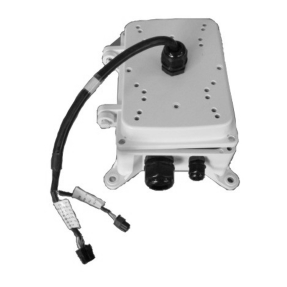
DESCRIZIONE PRODOTTO E TIPO DI IMPIEGO Il Power Box Sch.1092/708 è certificato IP66, quindi progettato per essere impiegato sia in interni che in esterni. L’involucro metallico contiene l’alimentatore per la Dome, i cavi di collegamento ed è anche possibile inserirvi la scheda di allarmi a 8 ingressi programmabili opzionale Sch.1092/709. - Page 3 Power Box. Nota Bene Se viene utilizzata una Dome Sch.1092/605 il cavo di collegamento esterno al Power Box deve essere ridotto in estensione fino alla fascia di riferimento posta sul cavo stesso e indicato in figura.
-
Page 4: Comandi E Regolazioni
POSIZIONAMENTO E COLLEGAMENTI CON UTILIZZO DELLA SCHEDA DI ALLARMI SCH.1092/709 COMANDI E REGOLAZIONI Qui di seguito, vengono riportate le tabelle relative alle regolazioni dei dip-switch presenti sulla scheda di allarme opzionale Sch.1092/709 installabile nel Power Box. COLLEGAMENTO TASTIERA COLLEGAMENTO DOME... - Page 5 DIP SW 1 (INDIRIZZO DOME) S w i t c h N O . Indirizzo ---- DIP SW 2 (PROTOCOLLO DI COMUNICAZIONE – BAUD RATE) Protocollo Baud rate Switch NO Protocollo PELCO-D Baud rate 2400bps 4800bps 9600bps 19200bps DIP SW 3 (SELEZIONE TIPO DI CONTATTO – NA/NC) Switch NO/Sensore Normalmente APERTO...
-
Page 6: Installazione
DIP SW 4 (NUMERO PB – TEMPO RITARDO ALLARME) SELEZIONE TIPO DI ALLARMI/PRESET TEMPO DI RITARDO ALLARME TIPO Dip-switch Ritardo in Sec. Dip-switch I dip-switch 1 – 2 – 3 selezionano il tipo di allarmi/preset gestiti dal Power Box. Tipo 1 e 2 solo per EASY Urmet: Tipo 1 : rilevazione allarmi dal N°... -
Page 7: Caratteristiche Tecniche
Collegare la linea seriale RS485 ai morsetti AA BB (cavo arancio + AA / cavo giallo – BB) ai morsetti della tastiera (come indicato in figura). Collegare il connettore con i fili rosso e nero alla scheda di allarmi Sch.1092/709 (come indicato in figura). -
Page 8: General Information
Keep this manual at hand so that you can refer to it when needed. PRODUCT DESCRIPTION AND TYPE OF USE The Power Box Ref.1092/708 is IP66 certified and designed for indoor and outdoor use. The metallic housing contains the power supply for the Dome, the connection cables and it is also possible to insert the optional Ref.1092/709 alarm card with 8 programmable inputs. -
Page 9: Important Safety Notes
Do not use volatile liquids (such as petrol, alcohol, solvents, etc.) or chemically treated clothes to clean the device to prevent deformation, deterioration or scratches to the surface finish. POSITIONING AND CONNECTION WITHOUT USING THE REF.1092/709 ALARM CARD After the place where to install the camera is found, follow the instructions below: Make the fixing holes according to the wall type (cement or wood) and prepare the fixing devices (screw anchors, screws, etc.) - Page 10 Power Box package. Important If a Dome Ref. 1092/605 is used, the external connection cable to the Power Box must be shortened up to the indicating band on the cable as indicated in the photo.
- Page 11 POSITIONING AND CONNECTIONS USING THE REF. 1092/709 ALARM CARD COMMANDS AND SETTINGS The following tables show the settings of the dip-switches present on the optional alarm card Ref.1092/709 that can be installed in the Power Box. KEYBOAR CONNECTION DOME CONNECTION...
- Page 12 DIP SW 1 (DOME ADDRESS) S w i t c h N r . Address ---- DIP SW 2 (COMMUNICATION PROTOCOL – BAUD RATE) Protocol Baud rate Switch Nr. Protocol PELCO-D Baud rate 2400bps 4800bps 9600bps 19200bps DIP SW 3 (CONTACT TYPE SELECTION – NO/NC) Switch Nr/Sensor Normallly OPEN Normallly CLOSED...
-
Page 13: Alarm Delay Time
DIP SW 4 (PB NUMBER – ALARM DELAY TIME) ACTIONS ALARM DELAY TIME Power Box Dip-switch Delay in Sec. Dip-switch The dip-switches 1 – 2 – 3 select the alarm/preset type managed by Power Box. Type 1 and 2 for Urmet EASY Dome only. Type 1 : alarm detection from nr. -
Page 14: Technical Characteristics
Power Box package. Important If a Dome Ref. 1092/605 is used, the external connection cable to the Power Box must be shortened up to the indicating band on the cable as indicated in the photo. - Page 15 Le coffret métallique étanche contient l’alimentation pour le dôme et les câbles de raccordement. Il est possible d’y mettre en place aussi une carte d’alarmes à 8 entrées programmables en option (Réf. 1092/709). Ce coffret Réf.1092/708 est IP66 et peut être utilisée en intérieur et extérieur. CONTENU DE L’EMBALLAGE •...
- Page 16 Refermer le Coffret en utilisant les vis précédemment retirées et en contrôlant visuellement l’étanchéité. Note En cas d’utilisation d’une Dome Réf.1092/605, le câble de raccordement extérieur au Coffret d’Alimentation doit être réduit en longueur jusqu’à la bande de référence présente sur le câble lui-même et indiquée dans la figure.
- Page 17 MISE EN PLACE ET RACCORDEMENTS AVEC UTILISATION DE LA CARTE D’ALARMES REF. 1092/709 PARAMETRAGE DE LA CARTE DE GESTION VERS LE CLAVIER DE COMMANDE VERS LE DÔME DS1092-228...
- Page 18 DIP SW 1 (ADRESSAGE DU DÔME) S w i t c h N r . Adressage ---- L’adresse 0 (zéro) est interdite dans les protocoles de commande DIP SW 2 (CHOIX DU PROTOCOLE ET VITESSE) Choix du protocole Vitesse Switch Nr. Protocol PELCO-D Vitesse...
- Page 19 DIP SW 4 (SELECTION DES PREPOSITIONS ET DELAI ENTRE ALARMES) CHOIX DU TYPE DE PREPOSITIONS TEMPO ENTRE ALARMES Coffret Dip-switch Delay in Sec. Dip-switch Les Switch 1 – 2 – 3 déterminent le type de prépositions gérés par la carte d’alarme. Les types 1-2 ne s'appliquent qu'aux modèles EASY Urmet.
-
Page 20: Caracteristiques Techniques
Brancher le câble série de la ligne RS-485 du clavier (livré de série avec ce dernier) sur les bornes AA BB. Brancher le connecteur avec les fils rouge et noir à la carte d’alarmes Réf. 1092/709 (voir figure). Brancher les câbles des capteurs d’alarme sur les bornes 1 et 8 d’entrée alarme Pour les caméras du type analogique, crancher le câble vidéo en provenance du dispositif vidéo... -
Page 21: Allgemeine Informationen
ALLGEMEINE INFORMATIONEN Sehr geehrter Kunde, Dank fűr den Kauf dieses Urmet Produkts. Dieses Dokument beschreibt die Installation und die Verwendung der Power Box Typ 1092/708. Vor der Installation des Zubehörteiles diese Anleitung lesen, die dessen korrekten und sicheren Gebrauch beschreibt. -
Page 22: Reinigung Des Geräts
WARNHINWEISE SPANNUNGSVERSORGUNG Dieses Gerät darf ausschließlich mit einer Spannung von 230V AC betrieben werden. SICHERHEITSHINWEISE Vermeiden Sie es, das Gerät Regen oder Feuchtigkeit auszusetzen, um einer Brandgefahr und Stromschlägen vorzubeugen. Keine Fremdkörper oder Flüssigkeiten in das Geräteinnere gelangen lassen. Sollte dies dennoch geschehen, das Gerät vom Stromnetz trennen und von Fachpersonal kontrollieren lassen. - Page 23 Verwendung der im Lieferumfang der Power Box enthaltenen Schrauben. Hinweis Wird ein Dome Typ 1092/605 verwendet, muss das Anschlusskabel außen an der Power Box gemäß des auf dem Kabel angegebenen und in der Abbildung angegebenen Bezugs verkürzt werden. BEZUGSBAND...
- Page 24 ANSCHLÜSSE UNTER VERWENDUNG ALARMKARTE TYP 1092/709 EINSTELLUNGEN Die folgende Ansicht (Abb. 1) zeigt eine Übersicht der Anschlussklemmen und der DIP-Schalter, die auf der im Deckel der Power-Box installierbaren Alarmkarte Typ 1092/709 zur Verfügung stehen. RS485-ANSCHLUSS TASTATUR RS485-ANSCHLUSS DOME Alarm 1...
- Page 25 DIP SCHALTER 1 (ADRESSE DOME) S c h a l t e r N r . Adresse ---- DIP SCHALTER 2 (KOMMUNIKATIONSPROTOKOLL – BAUD RATE) Protokoll Baud Rate Schalter Nr. Protokoll PELCO-D Baud Rate 2400bps 4800bps 9600bps 19200bps DIP SCHALTER 3 (AUSWAHL KONTAKTTYP – NO/NC) Schalter Nr./Sensor Normal OFFEN...
- Page 26 DIP SCHALTER 4 (PB NUMMER – ALARM VERZÖGERUNGSZEIT) AKTION ALARM VERZÖGERUNGSZEIT DIP-Schalter Verzög. in DIP-Schalter Sek. Die DIP-Schalter 1 – 2 – 3 selektieren den Alarm/Preset der von der Power Box verwaltet wird. Typ 1 und 2 nur für Urmet EASY. Typ 1 : Alarmerkennung von Nr.
- Page 27 Anschluss der seriellen Linie RS485 an die Klemmen AA und BB (orangefarbenes Kabel + AA / gelbes Kabel – BB) an die Klemmen der Tastatur anschließen (wie in der Abbildung). Den Verbinder mit dem roten und schwarzen Draht an die Alarmkarte Typ 1092/709 anschließen (wie in der Abbildung)..
-
Page 28: Technische Eigenschaften
Verwendung der im Lieferumfang der Power Box enthaltenen Schrauben. Hinweis Wird ein Dome Typ 1092/605 verwendet, muss das Anschlusskabel außen an der Power Box gemäß des auf dem Kabel angegebenen und in der Abbildung angegebenen Bezugs verkürzt werden. BEZUGSBAND TECHNISCHE EIGENSCHAFTEN Eingang Versorgungsspannung: .................. - Page 29 DESCRIPCIÓN DEL PRODUCTO Y UTILIZACIÓN La caja de conexiones Ref. 1092/708 tiene un grado de protección IP66 y está diseñada para funcionar en exterior o interior. La carcasa metálica contiene la fuente de alimentación del domo y os cables de conexión; también se le puede colocar la tarjeta de alarmas de 8 entradas programables opcional Ref.
-
Page 30: Advertencias De Seguridad
ADVERTENCIAS DE SEGURIDAD Alimentación Alimente este equipo únicamente con tensión eléctrica de 230 VCA. PRECAUCIONES DE SEGURIDAD Evite introducir objetos o sustancias líquidas en el equipo. Si esto se produjera de manera accidental, desconecte el equipo de la red eléctrica y haga que lo inspeccione personal cualificado. - Page 31 Nota Si se utiliza un domo Ref.1092/605, se debe reducir la extensión del cable de conexión exterior de la caja de conexiones hasta la banda de referencia presente en el cable e indicada en la figura.
- Page 32 UBICACIÓN Y CONEXIONES UTILIZANDO LA TARJETA DE ALARMAS REF. 1092/709 COMANDOS Y AJUSTES Las siguientes tablas muestran los ajustes de los dip-switches que se encuentran en la tarjeta de alarm opcional Ref. 1092/709 que se instala en la caja de conexiones.. CONEXIÓN A TECLADO CONEXIÓN A...
- Page 33 INTERRUPTOR DIP 1 (DIRECCIÓN DEL DOMO) N . º s w i t c h Dirección ---- INTERRUPTOR DIP 2 (PROTOCOLO COMUNICACIÓN, VELOCIDAD TRANSFERENCIA) Protocolo Velocidad de transferencia N.º switch Protocolo PELCO-D Velocidad de transferencia 2.400 bps 4.800 bps 9.600 bps 19.200 bps INTERRUPTOR DIP 3 (TIPO DE CONTACTO: NO/NC) N.º...
- Page 34 INTERRUPTOR DIP 4 (N.º CAJA CONEXIONES, RETARDO DE ALARMA) ACCIONES RETARDO DE ALARMA Caja de Interruptor DIP Interruptor DIP conexione Retardo 3 segundos 6 segundos 9 segundos Los interruptores DIP 1, 2 y 3 seleccionan el tipo de posición predefinida o alarma gestionada por la caja de conexiones.
-
Page 35: Instalación
Conecte la línea RS-485 a los terminales AA BB (cable naranja + AA / cable amarillo – BB) en los terminales del teclado (como se indica en la figura). Conecte el conector con los cables rojo y negro en la tarjeta de alarmas Ref. 1092/709 (como se indica en la figura).. -
Page 36: Características Técnicas
Nota Si se utiliza un domo Ref.1092/605, se debe reducir la extensión del cable de conexión exterior de la caja de conexiones hasta la banda de referencia presente en el cable e indicada en la figura.
Need help?
Do you have a question about the 1092 and is the answer not in the manual?
Questions and answers