Table of Contents
Advertisement
Quick Links
Rev. 7/14/2016
Receiving instructions:
After delivery, IMMEDIATELY remove the packaging from the product in a manner that preserves the packaging and
maintains the orientation of the product in the packaging; then inspect the product closely to determine whether it
sustained damage during transport. If damage is discovered during the inspection, immediately record a
complete description of the damage on the bill of lading. If the product is undamaged, discard the packaging.
Notes:
1) Compliance with laws, regulations, codes, and non-voluntary standards enforced in the location where the product
is used is exclusively the responsibility of the owner/end-user.
2) VESTIL is not liable for any injury or property damage that occurs as a consequence of failing to apply either:
a) Instructions in this manual; or b) information provided on product labels.
Table of Contents:
Signal Words.......................................................................................................................................... 2
Safe Use Recommendations...................................................................................................................... 2
Product Specifications.............................................................................................................................. 3
FIG. 1A: PMPS-50M exploded parts diagram & bill of materials........................................................................ 4
FIG. 1B: PMPS-50 exploded parts diagram & bill of materials.......................................................................... 5
FIG. 2: PMPS-60 exploded parts diagram & bill of materials.............................................................................6
FIGS. 3 - 8: AC and DC modular power unit wiring diagrams, exploded parts diagrams, and layouts.................. 7 - 12
Loading instructions............................................................................................................................ ... 12
FIGS. 9A-9B: Autoshifter Foot Pump Exploded Parts Diagram....................................................................... 13
Autoshifter Bill of Materials...................................................................................................................... 14
FIG. 10: Hydraulic Circuit Diagram (Manual Foot Pump)............................................................................. ... 14
Operation Instructions (Manual Units): Pump purging procedure; Cylinder purging procedure............................... 15
Troubleshooting: Manual Foot Pump......................................................................................................... 16
FIG. 11: Hydraulic Circuit Diagram (electrically powered units)........................................................................ 17
Operation Instructions (Electric Units): Lowering solenoid; Velocity fuse; Air bleeding procedure........................... 18
Battery Charger Operation...................................................................................................................... 18
Inspections & Maintenance..................................................................................................................... 19
Troubleshooting Guide........................................................................................................................... 20
Labeling Diagram................................................................................................................................... 21
Limited Warranty.................................................................................................................................... 22
Copyright 2016 Vestil Manufacturing Corp.
Vestil Manufacturing Corp.
2999 North Wayne Street, P.O. Box 507, Angola, IN 46703
Telephone: (260) 665-7586 -or- Toll Free (800) 348-0868
www.vestilmfg.com
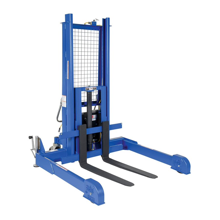
PM/PS-Series Pallet Handlers
Instruction Manual
Fax: (260) 665-1339
e-mail:
sales@vestil.com
Page 1 of 22
PMPS, MANUAL
Advertisement
Table of Contents
Troubleshooting

Related Manuals for Vestil PMPS Series


Summary of Contents for Vestil PMPS Series
-
Page 1: Table Of Contents
2) VESTIL is not liable for any injury or property damage that occurs as a consequence of failing to apply either: a) Instructions in this manual; or b) information provided on product labels. -
Page 2: Signal Words
Safe Use Recommendations: Vestil strives to identify foreseeable hazards associated with the use of its products. However, material handling is dangerous and no manual can address every conceivable risk. The end-user ultimately is responsible for exercising sound judgment at all times. -
Page 3: Product Specifications
77in. 36in. 3 - 50in. 66in. 429.2 kg 1,136.4 kg 853.4 lb. 4,000 lb. PMPS-60 8 - 37in. 4in. 58in. 101in. 87in. 36in. 3 - 60in. 66in. 387.9 kg 1,818.2 kg Copyright 2016 Vestil Manufacturing Corp. Page 3 of 22... - Page 4 Hydraulic foot pump, auto-shifter, 2- 11365 99-640-005 10x 3” speed 20-110-009 Bearing, ball 15-016-167 Bracket, top mount Machine bushing, low carbon, plain Thread cutting screw, slotted, type F, 33424 32416 finish, ”-18ga. zinc-plated, ”-18x ” Copyright 2016 Vestil Manufacturing Corp. Page 4 of 22...
- Page 5 Hex bolt, HHCS #2, zinc-plated, ”- ” inner diameter Belleville spring 11365 33354 10x 3” washer 37039 Nylock nut, zinc-plated, ”-10 37030 ” – 13 Nylon insert lock nut 99-024-003 Guard/cover/endcap/plug Copyright 2016 Vestil Manufacturing Corp. Page 5 of 22...
- Page 6 Hex bolt, HHCS #2, zinc-plated, ”- ” inner diameter Belleville spring 11365 33354 10x 3” washer 37039 Nylock nut, zinc-plated, ”-10 37030 ” – 13 Nylon insert lock nut 99-024-003 Guard/cover/endcap/plug Copyright 2016 Vestil Manufacturing Corp. Page 6 of 22...
-
Page 7: Figs. 3 - 8: Ac And Dc Modular Power Unit Wiring Diagrams, Exploded Parts Diagrams, And Layouts
29185 in. – 20 x 1in. TPHMS zinc-plated 23255 SHCS utility grade 33687 High collar lock washer 152400-03 Molded cord 150CCTM.OEM Connector, charge 3MT ST3540 1in. hook and loop press 10” Copyright 2016 Vestil Manufacturing Corp. Page 7 of 22... - Page 8 Valve, check FIG. 4: 12VDC modular power unit electrical circuit diagram Overcurrent & short-circuit protection as well as system disconnect must be provided. Limit switch or jumper wire used where applicable. Copyright 2016 Vestil Manufacturing Corp. Page 8 of 22...
- Page 9 Rev. 7/14/2016 PMPS, MANUAL FIG. 5A: 12VDC modular power unit layout (part 1 of 2) FIG. 5B: 12VDC modular power unit layout (part 2 of 2) Copyright 2016 Vestil Manufacturing Corp. Page 9 of 22...
- Page 10 – 20 x 1in. TPHMS zinc- plated 23255 SHCS utility grade 33687 High collar lock washer 152400-03 Molded cord 150CCTM.OEM Connector, charge 3MT ST3540 1in. hook and loop press 10” Copyright 2016 Vestil Manufacturing Corp. Page 10 of 22...
- Page 11 99 31 00 FIG. 7: 115VAC modular power unit electrical circuit diagram NOTE: Overcurrent & short-circuit protection as well as system disconnect must be provided. Limit switch or jumper wire used where applicable. Copyright 2016 Vestil Manufacturing Corp. Page 11 of 22...
-
Page 12: Loading Instructions
2.) ONLY use this device after you read and understand all operating procedures and safe use recommendations provided in this Owner's Manual. 3.) Lifter must never be overloaded. Copyright 2016 Vestil Manufacturing Corp. Page 12 of 22... -
Page 13: Figs. 9A-9B: Autoshifter Foot Pump Exploded Parts Diagram
Including 2 pressure ports and 2 intake/return ports allows the circuit configuration to be adapted to varied applications. The unused pressure and intake/return ports are each plugged with an Release pedal SAE #6 port plug. Copyright 2016 Vestil Manufacturing Corp. Page 13 of 22... -
Page 14: Autoshifter Bill Of Materials
(manual foot pump) in. x 18in. displacement cylinder with internal velocity fuse 2-speed foot pump Pressure check valve Pressure compensated flow control; 1GPM Pressure check valve Adj. Lowering valve pressure relief valve Copyright 2016 Vestil Manufacturing Corp. Page 14 of 22... -
Page 15: Operation Instructions (Manual Units): Pump Purging Procedure; Cylinder Purging Procedure
4. Repeat step 3 until air is completely removed from the cylinder (only oil flows from the bleed screw); 5. Check all of the hydraulic lines for oil leaks; then return the table to service. Copyright 2016 Vestil Manufacturing Corp. Page 15 of 22... -
Page 16: Troubleshooting: Manual Foot Pump
Remove valve and inspect for moving freely debris or non-operating spool 10. Forks rise part way and s. Air trapped in small pump chamber s. Perform “Pump purging then stop procedure” on p. 14. Copyright 2016 Vestil Manufacturing Corp. Page 16 of 22... - Page 17 Electric PMPS Operation Instructions: Pushbutton controls are standard equipment on PMPS series pallet handlers, i.e. a handheld controller as well as control buttons on the housing of the modular power unit. To raise or lower the fork carriage, press the appropriately marked button.
-
Page 18: Operation Instructions (Electric Units): Lowering Solenoid; Velocity Fuse; Air Bleeding Procedure
3) Examine the fuse (see p. 7). Replace only with a fuse having the same rating as the original fuse. 4) Determine battery condition. It may take some time before current begins to flow through a highly sulfated battery. Copyright 2016 Vestil Manufacturing Corp. Page 18 of 22... -
Page 19: Inspections & Maintenance
Step 2: Conduct a “Before each use”. If deformity, corrosion, rusting, or excessive wear of structural members is present, DO NOT use the pallet handler. Contact Vestil for instructions. If the carriage does not move smoothly or makes noise as it moves up or down the mast, apply a silicon wax or silicon spray to the inside of the mast frame. -
Page 20: Troubleshooting Guide
Binding cylinders. See 4 (r). ii. Air present in the hydraulic system causing To unlock, pressurize the hydraulic system. the velocity fuse to activate Copyright 2016 Vestil Manufacturing Corp. Page 20 of 22... -
Page 21: Labeling Diagram
E (inside MPU on oil tank) A: Label 824 D: Label 527 B: Label 643 C: Label 287 E: Label 206 (inside MPU on oil tank) F: Label 295 (on MPU cover) Copyright 2016 Vestil Manufacturing Corp. Page 21 of 22... -
Page 22: Limited Warranty
What is a “proper request”? A request for warranty service is proper if Vestil receives: 1) a photocopy of the Customer Invoice that displays the shipping date; AND 2) a written request for warranty service including your name and phone number. Send requests by any of the following...
Need help?
Do you have a question about the PMPS Series and is the answer not in the manual?
Questions and answers