
Related Manuals for Sorel Pool TDCM+


Summary of Contents for Sorel Pool TDCM+
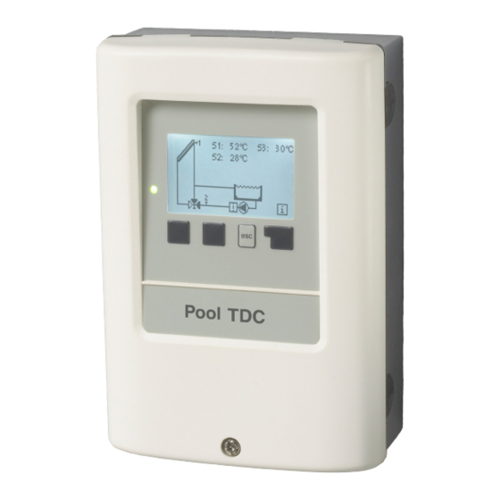
- Page 1 Pool Controller Pool TDCM+ Installation and operating instructions Read carefully before installation, commissioning and operation...
-
Page 2: Table Of Contents
Table of Contents page page Safety instructions 5.7. Delay / Switch-on delay Filter pump run time A.1. EC declaration of conformity 5.8. Hourly filter pump run time A.2. General instructions 5.9. Eco mode A.3. Explanation of symbols 5.10. Run time optimization A.4. Changes to the unit 5.11. Daily filtering time A.5. Warranty and liability 5.12. -
Page 3: Safety Instructions
Safety instructions A.1. EC declaration of conformity By affixing the CE mark to the unit the manufacturer declares that the Pool TDCM+ con- forms to the following relevant safety regulations: EC low voltage directive 2006/95/EC EC electromagnetic compatibility directive 2004/108/EC Conformity has been verified and the corresponding documentation and the EC declaration of conformity are kept on file by the manufacturer. A.2. General instructions These installation and operating instructions contain basic instructions and important information regarding safety, installation, commissioning, maintenance and the optimal use of the unit. Therefore these instructions must be read completely and understood by the installation technician/specialist and by the system user before installation, com- missioning and operation of the unit. The valid accident prevention regulations, VDE regulations, the regulations of the lo- cal power utility, the applicable DIN-EN standards and the installation and operating instructions of the additional system components must also be observed. The con- troller does not under any circumstances replace any safety devices which are to be provided by the customer! Installation, electrical connection, commissioning and maintenance of the unit may only be carried out by specialists who have the appropriate training. -
Page 4: Changes To The Unit
Safety instructions A.4. Changes to the unit Changes to the unit can compromise the safety and function of the unit or the entire system. Danger • Changes, additions to or conversion of the unit are not permitted without written authorisation from the manufacturer • It is likewise forbidden to install additional components that have not been tested together with the unit • If it becomes clear that safe operation of the unit is no longer possible, for example because of damage to the housing, turn the controller off immediately • Any parts of the unit or accessories that are not in perfect condition must be re- placed immediately • Use only original spare parts and accessories from the manufacturer • Markings made on the unit at the factory must not be altered, removed or made illegible • Only the settings described in these instructions may be used on the control- A.5. -
Page 5: Description Of Controller
Description of controller B.1. Electrical Mains voltage 230 VAC +/-10 % Mains frequency 50 - 60 Hz Power consumption 1.5 W - 2.3 W Internal fuse 4 A slow blow 250 V Protection category IP40 / IP 44 (only with the supplied seal kit)Protection class Overvoltage Category Degree of Pollution Category... -
Page 6: About The Controller
Description of controller B.3. About the controller The Pool Controller Pool TDCM+ facilitates efficient use and function control of your solar or heating system with your swimming pool. The device is impressive most of all for its functionality and simple, almost self-explanatory operation. For each step in the input process the individual entry keys are assigned to appropriate functions and explained. The controller menu contains headwords for the measured values and set- tings, as well as help texts or clearly-structured graphics. The BADU Logic 1 can be used as a solar controller for the various system variants ® illustrated and explained under “B.6. Hydraulic variants” on page 7. Important characteristics of the Pool TDCM+: Depiction of graphics and texts in an illuminated display Simple viewing of the current measurement values Analysis and monitoring of the system by means of statistical graphics, etc. Individual configuration of special functions Extensive menu settings with explanations Menu block activation to prevent unintentional setting changes Resetting to previously selected values or factory settings A wide range of additional functions... -
Page 7: Hydraulic Variants
Description of controller B.6. Hydraulic variants The following illustrations should be viewed only as schematic dia- grams showing the respective hydraulic systems and do not claim to be complete. The controller does not replace safety devices under any circumstances. Depending on the specific application, additional system components and safety components may be required, such as check Caution valves, non-return valves, safety temperature limiters, scalding protec- tors etc. and must therefore be provided. Pool with solar, ball valve and filter pump control Pool with solar, ball valve, auxiliary pump and filter pump control Pool with auxiliary heater, ball valve and filter Pool with heat pump, ball valve and filter pump pump control control Pool with filter pump control Pool with heat pump, heat exchanger and filter pump control... -
Page 8: Installation
Installation C.1. Wall installation Install the controller in dry areas only and under the ambient conditions de- scribed under “B.1. Specifications”. Caution 1. Unscrew cover completely C.1.1 . 2. Carefully pull upper part of housing from lower part. Terminal clamps are released during this process. 3. Set upper part of housing aside, being sure not to touch the electrics when doing 4. Hold the lower part of the housing up to the selected position and mark the 3 mounting holes. Make sure that the wall surface is as even as possible so that the housing does not become distorted when C.1.2. it is screwed on. 5. Using a drill and size 6 bit, drill 3 holes at the points marked on the wall and push in the plugs. -
Page 9: Electrical Connection
Installation C.2. Electrical connection Before working on the unit, switch off the power supply and secure it from being switched on again! Check for the absence of power! Electrical connections may only be made by a specialist and in compli- ance with the applicable regulations. Danger Do not use the controller if the housing shows visible damage. Low-voltage cables such as temperature sensor cables must be routed separately from the mains voltage cables. Feed temperature sensor ca- bles only into the left-hand side of the unit, and mains voltage cables only Caution into the right-hand side. The customer must provide an all-pole disconnecting device, e.g. -
Page 10: Installing The Temperature Sensors
Installation 1. Select necessary program/hydraulics. C.2.2. 2. Open controller casing (“C.1. W all installation” on page 8). 3. Strip cables by 55 mm max., insert, fit the strain relief devices, strip the last 8-9 mm of the wires. 4. Open the terminals using a suitable screwdriver (Fig. C.2.1.) and make electrical connections on the control- ler. 5. Refit terminal connection cover and fasten screw. 6. Switch on mains voltage and place controller in operation. C.3. -
Page 11: Terminal Connection Diagram
Installation D. Terminal connection diagram Low voltage Relays Mains Kleinspannungen Relais Mains max. 12 V Mains voltages 230 VAC Danger Caution Low voltage max. 12 VAC/DC Mains voltage 230 VAC 50-60 Hz Terminal Connection for Terminal Connection for S1 (2x) Collector Mains neutral conductor N S2 (2x) Pool Filter pump S3 (2x) Flow sensor (optional) Mains neutral conductor N Mains phase conductor L Mains neutral conductor N Ball valve, heat pump or auxiliary pump Ball valve The PE protective conductor must be... -
Page 12: Operation
Operation E.1. Display and input The display (1), with its extensive text and graphics mode, is almost self-explanatory, allowing easy operation of the controller. To change from the overview to the set- tings menu, press the „esc“ key. The green status LED (2) lights up when a solar requirement ist aktiv (Ball value on/ off) Other features of the LED are dis- cribed in nChapter Z.1. Inputs are made with 4 buttons (3 + 4), which have different functions depending Examples of display symbols: on the context. The „esc“ key (3) is always used to cancel Pump (rotates in operation) or exit a menu. Collector If applicable there will be a request for confirmation as to whether the changes Pool which have been made should be saved. Temperature sensor The function of each of the other three keys (4) is shown in the display line di-... -
Page 13: Commissioning Help
Commission E.2. Commissioning help The first time the controller is turned on and after the language and time are set, a query appears as to whether you want to para- metrise the controller using the commissioning help or not. The commissioning help can also be terminated or called up again at any time in the special functions menu. The commission- ing help guides you through the necessary ba- sic settings in the correct order, and provides brief descriptions of each parameter in the display. Pressing the “esc” key takes you back to the previous value so you can look at... -
Page 14: Menu Sequence And Menu Structure
Operation E.4. Menu sequence and menu structure The graphics or overview mode appears when no key has been press for 2 minutes or when the main menu is exited by press- ing “esc“. The up and down buttons are used to scroll through the list of sensors and relays. You can enter the main menu by pressing the “esc“ key. The following menus are available: Current temperature values with explana- 1. -
Page 15: Measurement Values
Measurement values 1. Measurement values The menu “1. Measurement values” serves to display the currently measured tempera- tures. The menu is closed by pressing the “esc” key or selecting “Exit measurement values”. The measurement values are explained with a help text when selected. Selecting “Overview” or “esc” exits the Info mode. -
Page 16: Statistics
Statistics 2. Statistics The menu “2. Statistics” is used for func- tion control and long-term monitoring of the system. The menu is closed by pressing the “esc” key or selecting “Exit statistics”. For analysis of the system data it is essential for the time to be set ac- curately on the controller. Please note that the clock only has a battery reserve for 24 hours and must therefore be reset afterwards. Improper operation or an incorrect time may result in data being deleted, recorded Achtung incorrectly or overwritten. The manufacturer accepts no liability for the recorded data! 2.1. Operating hours Display of operating hours of the pump connected to the controller; various time ranges (day-year) are available. 2.2. Average pool temperature Displays the average pool temperature. 2.3. Heat output Displays the system’s heat output. -
Page 17: Display Mode
Display mode 3. Display mode The menu “3. Display mode” is used to define the controller’s display for normal operation. This display appears whenever two min- utes go by without any key being pressed. The main menu appears again when a key is pressed. The menu is closed by pressing the “esc” key or selecting “Exit display mode”. 3.1. Schematic In graphics mode, the selected hydraulic systems are depicted with the measured temperatures and operating states of the connected consumers. -
Page 18: Operating Mode
Operating mode 4. Operating mode In the menu “4. Operating mode” the con- troller can either be placed in automatic mode, switched off or placed in a manual operating mode. The menu is closed by pressing the “esc” key or selecting “Exit operating mode”. 4.1. Automatic Automatic mode is the normal operating mode of the controller. Only automatic mode provides proper controller function taking into account the current temperatures and the parameters that have been set! After an interruption of the mains voltage the con- troller automatically returns to the last operating mode selected! 4.2. Manual The relay and thus the connected consumer are switched on and off, with no regard to the current temperatures and the parameters which have been set, by pressing a key. The measured temperatures are also shown to provide an overview and function... -
Page 19: Settings
Settings 5. Settings The necessary basic settings required for the control function are made in menu “5. Set- tings”. This does not under any cir- cumstances replace the safety facilities to be provided by the Caution customer! The menu is closed by pressing the “esc” key or selecting “Exit settings”. The following pages contain generally valid descriptions for the settings. Enumerations may vary. Caution 5.1. Tmin S1 Enable/start temperature at sensor 1 If this value is exceeded at sensor 1 and the other conditions are also met, then the controller switches the associated pump and/or ball value on. If the temperature at sensor 1 drops below this value by 5 °C, the pump and/or the valve are switched off again. Setting range: 0 °C ... 99 °C / Default: 20 °C 5.2. -
Page 20: T R1
Settings 5.3. ∆T R1 Switch-on/switch-off temperature difference for relay R1 If this temperature difference is reached, the ball value at R2 and the pump at R1 are switched on. When the temperature drops to ΔT-Off, pump / valve are switched off. Setting range: ΔT-On 4 °C ... 20 °C / Default 10 °C ΔT-Off 2 °C ... 9 °C / Default: 3 °C If the set temperature difference is too small, this may result in ineffec- tive operation, depending on the system and sensor positions. Caution Reference sensors are usually S1 and S2. If S3 is connected, the switch Off ΔT-Off is between S2 and S3. Caution 5.4. Tset S2 Targettemperature for sensor 2. Below this temperature the heating is switched on until Tsoll+Hysteresis is reached. Setting range: 0 °C ... 40 °C / Default: 20 °C 5.5. -
Page 21: Eco Mode
Settings 5.9. Eco mode When the Eco mode is inactive, the hourly run time and the solar operating hours are ignored when calculating the daily filter pump run times. The solar operating hours are also ignored when calculating the hourly filter pump run time. Setting range: On, Off 5.10. Run time optimization When the run time optimization is active, the „hourly filter pump run time“ is reduced in regards of the average pool temperature of the past hour. When the average pool temperature was 30 °C, the hourly filter pump run time is fully committed. When the average pool temperature was 20 °C, the hourly filter pump run time is halved (and the solar run time is subtracted afterwards). The runtime-to-time dependency is calculated in 5 % steps per °C. Example: 20 °C = 50 %, 25 °C = 75 %, 27 °C = 85 %, 30 °C = 100 % Setting range: off, daily 0:00 ... 23:59 hour / Default: daily 0:00 ... 23:59 hour 5.11. Daily filtering time Used to ensure that the filter system is at least running for the time set here regardless of temperature. Eco mode: The time the filter pump was running on this day is sub- tracted from the time span set here. Example: Daily filtering time is set to run between 16 and 19 o‘clock = 3 hours. The filter pump was already active for 2 hours during the day. -
Page 22: Seizing Protection
Protective functions 6.1. Seizing protection If the seizing protection is activated, the controller switches the relay in question and the connected consumer on every day at 12:00 (setting “daily”) or weekly on Sundays at 12:00 (setting “weekly”) for 5 seconds in order to prevent the pump and/or the ball value from sticking after an extended stationary period. Setting range R1: daily, weekly, off / Default: off Setting range R2: daily, weekly, off / Default: off 6.2. Frost protection A two-stage frost protection function can be activated. In stage 1 the controller switch- es the pump on for 1 minute every hour if the collector temperature drops below the set value “Frost stage 1”. If the collector temperature drops further to the set value “Frost stage 2” the controller switches the pump on continuously. If the collector temperature then exceeds the value “Frost stage 2” by 2 °C, the pump switches off again. -
Page 23: Special Functions
Special functions 7. Special functions The menu “7. Special functions” is used to set basic items and expand functions. Other than the time, all settings may only be made by a special- Caution ist. The menu is closed by pressing the “esc” key or selecting “Exit special functions”. 7.1. Program selection The suitable hydraulic variant for the specific application is selected and set here (see “B.6. Hydraulic variants” on page 7). The associated diagram is displayed after pressing “Info”. Setting range: 1 ... 3 / Default: 1 Normally the program selection is made only once during initial commis- sioning by the specialist. Incorrect program selection can lead to unpre- dictable errors. Caution 7.2. Time and date This menu is used to set the current time and date. For analysis of the system data it is essential that the time is set accu- rately on the controller. Please note that the clock has a 24 hour battery reserve if the mains voltage is interrupted and must therefore be reset... -
Page 24: Commissioning
Special functions 7.4. Commissioning Starting the commissioning help guides you through the basic settings necessary for commissioning in the correct order and provides brief descriptions of each parameter in the display. Pressing the “esc” key takes you back to the previous value so you can look at the selected setting again or adjust it if desired. Pressing the “esc” key more than once takes you back to the selection mode, thus cancelling the commissioning help. (See also E.2). May only be started by a specialist during commissioning! Observe the explanations for the individual parameters in these instructions and check whether further settings are necessary for your application. Caution 7.5. Factory settings All of the settings that have been made can be reset, thus returning the controller to its delivery state. The entire parametrisation, analyses etc. of the controller will be lost ir- revocably. The controller must then be commissioned once again. Caution... -
Page 25: Heat Quantity
Special functions 7.6. Heat quantity A simple heat metering function for basic system control can be activated in this menu. Ad- ditional settings regarding the glycol, the percentage of gylcol and the flow rate of the system are required. Additionally Offset ∆T can be used to enter a correction value to compensate for the temperature difference between flow and return temperature. Since the collector and the pool temperature are used to calculate the heat quantity, deviations from the dis- played temperature can occur. Example: Displayed collector temp. 40 °C, measured flow temp. 39 °C, displayed stor- age temp. 30 °C, measured return temp. 31 °C means a setting of -20 % (Displayed ∆T 10 K, actual ∆T 8 K => -20 % correction value) Heat quantity: on, off / Default: off Flow rate setting: 10 ... 5000 l/h / Default: 500 l/h Offset ΔT setting: -50 % ... +50 % / Default: 0 % Heat quantity data is only an approximation for function control of the system. -
Page 26: Menu Lock
Menu lock Menu lock The menu “8. Menu lock” can be used to secure the controller from unintentional changing of the set values. The menu is closed by pressing the “esc” key or selecting “Exit menu lock”. The menus listed below remain completely accessible despite the menu lock being activated and can be used to make adjustments if necessary: Measurement values Analysis Display mode 7.2. Time and date Menu lock Service values To lock the other menus select “Menu lock on”. To enable the menus again select “Menu lock off”. Setting range: on, off / Default: off... -
Page 27: Service Values
Service values Service values The menu “9. Service values” can be used for remote diagnosis by a specialist or the manu- facturer in the event of an error etc. Enter the values at the time when the error occurs e.g. in the table. Caution The menu can be closed at any time by press- ing the “esc” key. -
Page 28: Language
Language 10. Language The menu “10. Language” can be used to select the language for the menu guid- ance. This is queried automatically during initial commissioning. The choice of lan- guages may differ, however, depending on the device design. Default: Deutsch... -
Page 29: Malfunctions
Malfunctions Z.1 Malfunctions with error messages If the controller detects a malfunction, the red light flashes and the warning symbol also appears in the display. If the error (LED flashes + is no longer present, the warning symbol warning symbol) changes to an info symbol and the red light no longer flashes. To obtain more detailed information on the error, press the key under the warning or info symbol. Do not try to deal with this yourself. Consult a specialist in the Danger event of an error! Possible error messages: Notes for the specialist: Sensor x faulty ----------------> Means that either the sensor, the sensor input at the controller or the connecting cable is / was faulty. -
Page 30: Replacing The Fuse
Malfunctions Z.2. Replacing the fuse Repairs and maintenance may only be performed by a specialist. Before working on the unit, switch off the power supply and secure it from being Danger switched on again! Check for the absence of power! Only use the spare fuse supplied or a fuse of the same design with the following specifications: T 4 A / 250 V Danger If the mains voltage is switched on and Z.2.1 the controller still does not function or Fuse display anything, the internal device fuse may be faulty. In that case, open the de- vice as described under C, remove the old fuse and check it. Replace the faulty fuse with a new one, locate the external source of the error (e.g. pump) and repair or replace it. Then recommission the controller and check the function of the switch outputs in manual mode first as described under 4.2. Z.3. Maintenance In the course of the general annual maintenance of your heating and solar system system you should also have the functions of the controller checked by a specialist and have the settings optimised if necessary. Caution Performing maintenance: - Check the time and date (see “7.2. Time and date” on page 23) - Assess/check plausibility of analyses (see “2. Statistics” on page 16) - Check the error memory (see “2.5. Message log” on page 16) - Verify/check plausibility of the current measurement values (see “1. Measurement values”... - Page 31 Notes The service values (see 9.) include not only current measurement values and operating states, but also all of the settings for the controller. Write the service values down once after commissioning has been successfully completed. In the event of uncertainty as to the control response or malfunctions the service values are a proven and successful method for remote diagnosis. Write the service values down (see 9.) at the time the suspected malfunc- tion occurs. Send the service value table by fax or e-mail with a brief description of the error to the specialist or manufacturer. To protect against loss of data, record any analyses and data that are par- ticularly important to you (see 2.) at regular intervals. Filter pump party function: When the “esc” key is pressed for 3 seconds the filter pump switches on for 5 hours. This can be canceled by pressing the “esc” key again for 3 seconds. Notes of commissioning:...
- Page 32 Hydraulic variant set: Commissioned on: Commissioned by: Final declaration: Although these instructions have been created with the greatest possi- ble care, the possibility of incorrect or incomplete information cannot be excluded. Subject as a basic principle to errors and technical changes. Ihr Fachhändler: Hersteller: SOREL GmbH Mikroelektronik Reme-Str. 12 D - 58300 Wetter Tel. +49 (0)2335 682 77 0 Fax +49 (0)2335 682 77 10 www.sorel.de info@sorel.de...
Need help?
Do you have a question about the Pool TDCM+ and is the answer not in the manual?
Questions and answers