
Related Manuals for Cebora Power Tig 1540 DC-HF


Summary of Contents for Cebora Power Tig 1540 DC-HF
- Page 1 CEBORA S.p.A. POWER TIG 1540 DC-HF POWER SOURCE art. 271 SERVICE MANUAL 3.302.212 12/01/06...
-
Page 2: Table Of Contents
CEBORA S.p.A. CONTENTS - GENERAL INFORMATION......................3 - Introduction............................3 - General service policy........................3 - Safety information..........................3 - Electromagnetic compatibility.......................3 - SYSTEM DESCRIPTION........................4 - Introduction............................4 - Technical specifications.........................4 - Description of power source art. 271.....................4 - MAINTENANCE ..........................5 - Periodic inspection, cleaning. -
Page 3: General Information
It is forbidden to attempt to repair damaged electronic boards or modules; replace them with original Cebora spare parts. 1.3 - Safety information. The safety notes provided in this manual are an integral part of those given in the Instruction Manual. -
Page 4: System Description
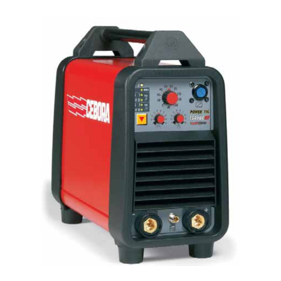
2 - SYSTEM DESCRIPTION 2.1 - Introduction. The POWER TIG 1540 DC-HF is a system for MMA and TIG welding, with arc starting in both contact and high frequency mode. It is made up of an electronic power source (art. 271), and a set of accessories to adapt to various applications (see list in Sales Catalogue). -
Page 5: Maintenance
CEBORA S.p.A. 3 - MAINTENANCE WARNINGS ANY INTERNAL INSPECTIONS OR REPAIRS MUST BE CARRIED OUT BY QUALIFIED PERSONNEL. BEFORE BEGINNING MAINTENANCE OPERATIONS, UNPLUG THE MACHINE FROM THE MAINS AND WAIT FOR THE INTERNAL CAPACITORS TO DISCHARGE (2 MINUTES). 3.1 - Periodic inspection, cleaning. -
Page 6: Starting The Power Source
CEBORA S.p.A. NOTE Operations preceded by this symbol refer to operator actions. ♦ Operations preceded by this symbol refer to machine responses that must occur following an operator action. 3.2.2 - Starting the power source. System shut off and disconnected from the mains. -
Page 7: Mma Operation
CEBORA S.p.A. Press the start button and hold it down for approximately 5 seconds. ♦ The pre-gas phase begins; the high frequency is then generated to start the arc, as well as the power source output voltage. ♦ After approximately two seconds, the output voltage and high frequency to start the arc are no longer generated, and the post-gas phase begins (TIG operation with HF stops if there is no current at the power source output after start-up). -
Page 8: Troubleshooting
CEBORA S.p.A. 3.3 - Troubleshooting. WARNINGS ANY INTERNAL INSPECTIONS OR REPAIRS MUST BE CARRIED OUT BY QUALIFIED PERSONNEL. BEFORE REMOVING THE PROTECTIVE GUARDS AND ACCESSING INTERNAL PARTS, DISCONNECT THE POWER SOURCE FROM THE MAINS AND WAIT FOR THE INTERNAL CAPACITORS TO DISCHARGE (2 MINUTES). -
Page 9: Power Source Powered, Fan (16) Stopped
CEBORA S.p.A. ♦ Check the wiring between CN2 power board (29) and CN2 panel board (26). ♦ Disconnect temporarily, with power source off, connector CN2 on panel board (26) and verify terminals 1 and 2 of CN2 on panel board (26) are not in short circuit. - Page 10 CEBORA S.p.A. SIGNALING TEST. Upon start-up, after the lamp-test, pressing button (A) several times the “Process” and “Mode” selection is repeated in sequence, indicated by leds F, E, D, C and B that lit in sequence. Correct? ♦ Check the wiring between the CN2 power board (29) and CN2 panel board (26).
-
Page 11: In Tig, The Start Button Produces No Effect
CEBORA S.p.A. 3.3.4 - In TIG, the start button produces no effect. START COMMAND TEST. Power board (29), connector CN1, terminals 4(+) and 8(-) = 0 Vdc (start), with torch button pressed (+5 Vdc with button released). Correct? ♦ Check the wiring between CN1 power board (29) and CN1 panel board (26). -
Page 12: In Tig, Gas Flows From The Torch, The Arc Does Not Start, High Frequency Missing
CEBORA S.p.A. 3.3.6 - In TIG, gas flows from the torch, the arc does not start, high frequency missing. WARNING DURING THE FOLLOWING TESTS LEAVE FREE FROM CONNECTIONS AND DO NOT TOUCH THE OUTPUT TERMINAL NEGATIVE (P) OF THE POWER SOURCE. THE EVENTUAL PRESENCE OF HIGH VOLTAGE AND HIGH FREQUENCY IS DANGEROUS FOR OPERATOR AND CAN DAMAGE THE INSTRUMENTS OR THE POWER SOURCE. -
Page 13: In Open Circuit Operation, The Output Voltage Is Not Regular
CEBORA S.p.A. ♦ Make sure the good insulation of the HF generator circuit devices installed on printed circuit board of power board (29), and remove eventual traces of dirt or powder that can create short circuits between the devices. ♦ Check the distance between the tips of the discharger SC1 (correct = 0.9 mm.). -
Page 14: In Resistive Load Operation, The Output Voltage Is Not Regular
CEBORA S.p.A. 3.3.8 - In resistive load operation, the output voltage is not regular. WARNING FOR THE FOLLOWING TESTS SET OPERATION TIG WITH HIGH FREQUENCY, LED (C) LIT, BUT DISCONNECT THE HF TRANSFORMER (27) PRIMARY CIRCUIT TERMINALS FROM “HT” TERMINALS OF POWER BOARD (29) TO AVOID HF GENERATION. -
Page 15: In Tig, Arc Unstable, Welding Irregular
CEBORA S.p.A. 3.3.9 - In TIG, arc unstable, welding irregular. NOTE In TIG, the welding quality may not be acceptable due to current instability. In this case we recommend switching to MMA operation, and performing welding tests. MMA WELDING QUALITY TEST. -
Page 16: Components List
CEBORA S.p.A. 4 - COMPONENTS LIST 4.1 - Power source art. 271: see file ESP271.pdf enclosed at the end of the manual. 4.2 - Components table: see file ESP271.pdf enclosed at the end of the manual. 4.3 - Spare parts list. - Page 17 CEBORA S.p.A. 5.2.2 - Topographical drawing. 3.302.212 12/01/06...
-
Page 18: Panel Board (26) Code 5.602.183
CEBORA S.p.A. 5.3 - Panel board (26) code 5.602.183. 5.3.1 - Topographical drawing. 5.3.2 - Connector table. Connector Terminals Function “+” input for torch potentiometer. torch potentiometer cursor output. “-“ input for torch potentiometer. “START” signal output. “DOWN” signal output.
Need help?
Do you have a question about the Power Tig 1540 DC-HF and is the answer not in the manual?
Questions and answers
Que precio tiene colombia