
Related Manuals for Bosch Rexroth IndraControl VDP 16.3


Summary of Contents for Bosch Rexroth IndraControl VDP 16.3
- Page 1 IndraControl VDP 16.3, VDP 40.3, VDP 60.3 Operator Display Project Planning Manual Edition 07 R911323862...
- Page 2 2019-05 CDI+ interface supple‐ mented, switching time of Y-repeater updated Copyright © Bosch Rexroth AG 2019 All rights reserved, also regarding any disposal, exploitation, reproduction, editing, distribution, as well as in the event of applications for industrial property rights. Liability...
-
Page 3: Table Of Contents
Compatibility test..........................15 Dimensions, Installation and Wiring................17 Housing dimensions..........................17 5.1.1 Housing dimensions VDP 16.3......................17 5.1.2 Housing dimensions VDP 40.3......................19 5.1.3 Housing dimensions VDP 60.3......................21 Installation............................. 22 5.2.1 Installation Notes..........................22 R911323862_Edition 07 Bosch Rexroth AG... - Page 4 IndraControl VDP 16.3/40.3/60.3/90.3/92.3..............43 Touch screen............................43 VDP USB monitor service........................43 9.2.1 Function............................. 43 9.2.2 Installing, uninstalling and exiting the service..................43 Environmental protection and disposal ............... 45 10.1 Environmental protection........................45 10.2 Disposal..............................45 Bosch Rexroth AG R911323862_Edition 07...
- Page 5 Uninterruptible power supply (UPS)....................50 11.5.5 Connecting cables for CDI interface....................50 11.5.6 Connecting cables for the USB interface................... 51 11.5.7 USB connecting cable with increased noise immunity..............52 Service and support..................... 53 Index..........................55 R911323862_Edition 07 Bosch Rexroth AG...
- Page 6 IndraControl VDP 16.3, VDP 40.3, VDP 60.3 Operator Dis‐ play Bosch Rexroth AG R911323862_Edition 07...
-
Page 7: System Presentation
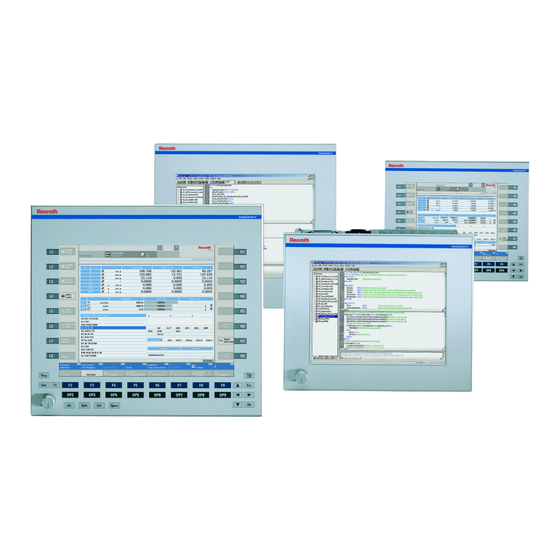
VDP 16.3 – Customized design for Bosch – – Display 304.8 mm TFT (12") Touch screen Keys (foil keyboard) 16 machine function keys Tab. 1-2: Characteristic features of the VDP 16.3 devices R911323862_Edition 07 Bosch Rexroth AG... -
Page 8: Displays With Foil Keyboard
Danger of destruction of the touch screen if NOTICE operated with inappropriate objects. Operate the touch screen only with your finger or with a touch pen suitable for capacitive touch screens. Bosch Rexroth AG R911323862_Edition 07... -
Page 9: Vdp Variants
IndraControl VDP 16.3, VDP 40.3, VDP 60.3 Operator Display 3/57 System presentation 1.2.5 VDP Variants VDP with Touch Screen Fig. 1-1: VDP with touch screen R911323862_Edition 07 Bosch Rexroth AG... - Page 10 4/57 IndraControl VDP 16.3, VDP 40.3, VDP 60.3 Operator Dis‐ play System presentation VDP With Foil Keyboard and 16 Machine Function Keys Fig. 1-2: VDP with foil keyboard and 16 machine function keys Bosch Rexroth AG R911323862_Edition 07...
-
Page 11: Accessories
CDI+ interfaces is not possible. Commissioning Mount the device properly (see chapter 5 "Dimensions, Installation and Wiring" on page 17). Connect the device to the de-energized control cabinet PC; then connect the 24 V supply voltage. R911323862_Edition 07 Bosch Rexroth AG... - Page 12 6/57 IndraControl VDP 16.3, VDP 40.3, VDP 60.3 Operator Dis‐ play Bosch Rexroth AG R911323862_Edition 07...
-
Page 13: Important Instructions On Use
It must be ensured that the products are installed as specified in the documentation. 2.1.2 Areas of Use and Application The Rexroth VDP 16.3/40.3/60.3 displays are passive operating and visualization terminals forming a PC-based machine operating terminal when used with an industrial PC. R911323862_Edition 07 Bosch Rexroth AG... -
Page 14: Inappropriate Use
● the intended applications have not expressly been allowed by Rexroth. It is imperative that you also note the information given in the general notes on safety! Bosch Rexroth AG R911323862_Edition 07... -
Page 15: Using Safety Instructions
In case of non-compliance with this safety instruction, death or serious injury can occur. CAUTION In case of non-compliance with this safety instruction, minor or moderate injury can occur. NOTICE In case of non-compliance with this safety instruction, material damage can occur. R911323862_Edition 07 Bosch Rexroth AG... -
Page 16: Symbols Used
If this symbol is on your device, you have to observe the documentation on the device. The respective documentation informs on the type of hazard as well as krax the steps required to avoid this hazard. Bosch Rexroth AG R911323862_Edition 07... -
Page 17: Technical Data
Light gray Bosch design Operation Touch control Touch screen Touch control operation and switching elements Degree of Front panel IP 65 acc. to DIN EN 60 529 protection Front Type 1 acc. to NEMA (UL) R911323862_Edition 07 Bosch Rexroth AG... -
Page 18: Voltage Supply
Air pressure Up to 3,000 m above sea Up to 3,000 m above sea Up to 3,000 m above sea level acc. to EN 61131-2 level acc. to EN 61131-2 level acc. to EN 61131-2 Bosch Rexroth AG R911323862_Edition 07... -
Page 19: Standards
Degrees of protection (including housings and installation compartments) EN 60 068-2-6 Vibration test EN 60 068-2-27 Shock test EN 60 721-3-1 and Climatic class EN 60 721-3-3 Tab. 4-6: Standards used 4.4.2 CE Marking Declaration of Conformity R911323862_Edition 07 Bosch Rexroth AG... -
Page 20: Certification, Ul And Csa
● C22.2 no. 142-M1987 (CSA) UL file no. E210730 However, there can be combinations or extension stages with a limited or missing certification. Thus, verify the registration according to the UL marking on the device. Bosch Rexroth AG R911323862_Edition 07... -
Page 21: Wear Parts
Bosch Rexroth might occur. For this reason, before using the respective material a compatibility test has to be carried out for new materials (e. g. lubricants and cleaning agents) and our housing or our housing materials. R911323862_Edition 07 Bosch Rexroth AG... - Page 22 16/57 IndraControl VDP 16.3, VDP 40.3, VDP 60.3 Operator Dis‐ play Bosch Rexroth AG R911323862_Edition 07...
-
Page 23: Dimensions, Installation And Wiring
350 mm and the height is 290 mm. All values in the illustrations are given in mm. Fig. 5-1: Dimensions: Front panel of the VDP 16.3DB Fig. 5-2: VDP 16.3BK: Top view R911323862_Edition 07 Bosch Rexroth AG... - Page 24 The front panel width of the VDP 16.3AK is 360 mm and the height is 300 mm. It has no USB connection. Fig. 5-4: Dimensions: Front panel of the VDP 16.3AK Fig. 5-5: VDP 16.3AK: Top view Fig. 5-6: VDP 16.3AK: Left view Bosch Rexroth AG R911323862_Edition 07...
-
Page 25: Housing Dimensions Vdp 40.3
Fig. 5-7: Dimensions: Front panel of the VDP 40.3BI devices The front panels of the VDP 40.3DE, -BI, -DF and VDP 40.3DG have the same dimensions. Fig. 5-8: VDP 40.3BI and VDP 40.3DE: Top view R911323862_Edition 07 Bosch Rexroth AG... - Page 26 The front panel width of the VDP 40.3AL is 417 mm and the height is 380 mm. It has no USB connection. Fig. 5-10: Dimensions: Front panel of the VDP 40.3AL devices Fig. 5-11: VDP 40.3AL: Top view Fig. 5-12: VDP 40.3AL: Left view Bosch Rexroth AG R911323862_Edition 07...
-
Page 27: Housing Dimensions Vdp 60.3
483 mm and the height is 400 mm. All values are given in mm. IndraControl V Fig. 5-13: Dimensions: Front panel of the VDP 60.3 Fig. 5-14: VDP 60.3: top view R911323862_Edition 07 Bosch Rexroth AG... -
Page 28: Installation
4. Fasten the display by screwing the nuts at the rear side of the mounting bolts. Damage to the mechanics caused by wrong NOTICE tightening torque. Fasten the screws with the respective mounting torques specified in the following table. Bosch Rexroth AG R911323862_Edition 07... -
Page 29: Mounting Dimensions Vdp 16.3
23/57 Dimensions, Installation and Wiring Thread Mounting torque M2,5 0.4 Nm 0.7 Nm 1.4 Nm 2.8 Nm Tab. 5-3: Tightening torques 5.2.3 Mounting Dimensions VDP 16.3 Fig. 5-16: Mounting dimensions of the VDP 16.3 devices R911323862_Edition 07 Bosch Rexroth AG... -
Page 30: Mounting Dimensions Vdp 40.3
24/57 IndraControl VDP 16.3, VDP 40.3, VDP 60.3 Operator Dis‐ play Dimensions, Installation and Wiring 5.2.4 Mounting dimensions VDP 40.3 Fig. 5-17: Mounting dimensions of the VDP 40.3 devices Bosch Rexroth AG R911323862_Edition 07... -
Page 31: Mounting Dimensions Vdp 60.3
IndraControl VDP 16.3, VDP 40.3, VDP 60.3 Operator Display 25/57 Dimensions, Installation and Wiring 5.2.5 Mounting dimensions VDP 60.3 231.5 231.5 bore diameter 5 mm (for M4 mounting bolt) Fig. 5-18: Mounting dimensions of the VDP 60.3 devices R911323862_Edition 07 Bosch Rexroth AG... -
Page 32: Electric Connection
Power supply units, whose net connection is designed for overvoltage category II, are to be connected to a net voltage with overvoltage category II, refer to fig. 5-19 "Power routing 230 V" on page Bosch Rexroth AG R911323862_Edition 07... -
Page 33: Power Routing 400 V
VDP xx.3 and VPB 40.3 and VSB 40.3 is recommended. If the functional earth is wired at a neutral point, also connect the control cabinet PC (VPB 40.3, VSB 40.3) to this neutral point. R911323862_Edition 07 Bosch Rexroth AG... -
Page 34: Control Cabinet Pc And Display At Ups
6 mm ² connect to FE of the UPS (VAU 01.1). 10 mm² (green/yellow) Fig. 5-22: PC (VSB 40.3, VSP xx.3, VPB 40.3, VPP xx.3) connected to an UPS. Display (VDP xx.3) not connected to an UPS Bosch Rexroth AG R911323862_Edition 07... -
Page 35: Display And Operating Components
LEDs displays an error or a note. Depending on the connected control cabinet PC, not all LEDs are activated. Therefore, not all messages are displayed. For further information, please refer to the relevant documentation of the control cabinet PC. R911323862_Edition 07 Bosch Rexroth AG... -
Page 36: Cdi
For the language-independent foil keyboard no language-dependent keyboard driver is to be installed. The preinstalled English keyboard driver can also be used for user interfaces of other languages. Therefore, do not change the delivery settings. Bosch Rexroth AG R911323862_Edition 07... -
Page 37: Position Of The Keys
<CTRL> + <SHIFT> + <ALT> + <F2> <CTRL> + <SHIFT> + <ALT> + <F9> Prog <CTRL> + <SHIFT> + <ALT> + <Q> INFO <CTRL> + <SHIFT> + <ALT> + <I> Tab. 6-3: Key code for the VDP 16.3 and VDP 40.3 R911323862_Edition 07 Bosch Rexroth AG... - Page 38 Bit 5 Bit 4 Bit 3 Bit 2 Bit 1 Bit 0 Bit 7 Bit 6 Bit 5 Bit 4 Bit 3 Bit 2 Bit 1 Bit 0 Tab. 6-5: M-key assignment at the Profibus DP Bosch Rexroth AG R911323862_Edition 07...
-
Page 39: Touch Screen
Start the calibration via the preinstalled "IPCMnt.exe" maintenance program. The program is to be found under Start ▶ Program Files ▶ Bosch Rexroth. The icons available on the touch screen depend on the used application software. - Page 40 34/57 IndraControl VDP 16.3, VDP 40.3, VDP 60.3 Operator Dis‐ play Bosch Rexroth AG R911323862_Edition 07...
-
Page 41: Interfaces
1,5/3-ST-3,5 XUSB1/2 At all 2 USB interfaces USB socket, USB plug, devices 4-pin, type A 4-pin, type A XUSB3/4 At all 2 USB interfaces USB socket, USB plug, devices 4-pin, type A 4-pin, type A R911323862_Edition 07 Bosch Rexroth AG... -
Page 42: S1 Dip Switch
USB 1.1. (max. data rate at full speed: 12 Mb/s). Cable length max. 30 m between control cabinet PC and VDP (stand‐ ard USB mode) The USB connection is executed in the USB1.1 mode. The S1 switch 2 must be in the "OFF" position. Bosch Rexroth AG R911323862_Edition 07... -
Page 43: 24 V Dc Voltage Supply
UPS. The user can carry out actions manually when there is a power failure of 24 V or if the control cabinet PC is switched off while the PC is shut down. 2. Direct connection to the 24 V supply voltage. R911323862_Edition 07 Bosch Rexroth AG... -
Page 44: Xusb Interfaces
The USB connections on the VDP 16.3/40.3/60.3 only support USB1.1 because the data is transferred to the control cabinet PC by using the XSER interface. If USB2.0 is required on the VDP 16.3/40.3/60.3, it can be implemented connecting XUSBIN connection Bosch Rexroth AG R911323862_Edition 07... -
Page 45: Xser And Xvid Interfaces
NOTICE and in the control cabinet PC if CDI cables are plugged and removed when voltage is applied without using a functional earth for both devices. The functional earthing (FE) is always to be used. R911323862_Edition 07 Bosch Rexroth AG... -
Page 46: Xcdi+Rx Interface
The CDI+ interface includes the data interface as well as the image transfer. Connect the control cabinet PC to the operating display using the ready- made cables (see chapter 11.5.5 "Connecting cables for CDI interface" on page 50) available as accessory. Bosch Rexroth AG R911323862_Edition 07... -
Page 47: Maintenance
LCD display A fading backlight causes a progressive deterioration of the readability of the LCD display, so that a backlight replacement is necessary. For further information, please contact the Bosch Rexroth Service. R911323862_Edition 07 Bosch Rexroth AG... - Page 48 42/57 IndraControl VDP 16.3, VDP 40.3, VDP 60.3 Operator Dis‐ play Bosch Rexroth AG R911323862_Edition 07...
-
Page 49: Indracontrol Vdp 16.3/40.3/60.3/90.3/92.3
All VDP operating displays delivered after the 1st of April 2015. 9.2.2 Installing, uninstalling and exiting the service Bosch Rexroth provides the file "VDP_USB_Monitor_Service_1.2.0.0.zip" upon request. To install, proceed with the following steps: 1. Create a "VDP_USB_Monitor_Service" folder in the "C:\Support\Rexroth \"... - Page 50 3. Next, select "Cmd" in the search results, right-click to open the context menu and select "Run as administrator". 4. Click on Yes to confirm the user account control prompt. 5. Go command line window "C:\Support\Rexroth \VDP_USB_Monitor_Service" then enter "VDP_USB_Monitor_Service - remove". Bosch Rexroth AG R911323862_Edition 07...
-
Page 51: Environmental Protection And Disposal
Batteries and accumulators can contain hazardous substances which can harm the environment or people's health when improperly stored or disposed After use, the batteries or accumulators contained in Rexroth products must be properly disposed of according to the country-specific collection systems. R911323862_Edition 07 Bosch Rexroth AG... - Page 52 Plastic parts of the products may contain flame retardants. These plastic parts are labeled according to EN ISO 1043. They have to be recycled separately or disposed of according to the applicable legal provisions. Bosch Rexroth AG R911323862_Edition 07...
-
Page 53: Ordering Information
(MTX)... . .= BK 12", touch screen ..= DB Customized design Bosch : 12", touch screen (suitable for food industry) = AK Additional option Without. -
Page 54: Vdp 40.3
..= DI Customized design Bosch: 15", touch screen..= AL Additional option Without..... .= N Control panel interface CDI . -
Page 55: Vdp 60.3
Without ........= NN Fig. 11-3: Type code VDP 60.3 R911323862_Edition 07 Bosch Rexroth AG... -
Page 56: Accessories
RKB0008/001,0 (*******-*******-*******) R911171485 Length: 1 m RKB0008/002,5 (*******-*******-*******) R911170151 Length: 2.5 m RKB0008/005,0 (*******-*******-*******) R911170152 Length: 5 m RKB0008/010,0 (*******-*******-*******) R911170153 Length: 10 m RKB0008/015,0 (*******-*******-*******) R911171183 Length: 15 m RKB0008/020,0 (*******-*******-*******) R911171184 Length: 20 m Bosch Rexroth AG R911323862_Edition 07... -
Page 57: Connecting Cables For The Usb Interface
Connecting cables to the control cabinet PC Malfunctions of the UPS if USB cables longer NOTICE than 3 m are used. The maximum length allowed for the USB connecting cable for the UPS is 3 R911323862_Edition 07 Bosch Rexroth AG... -
Page 58: Usb Connecting Cable With Increased Noise Immunity
RKB0023/001,0 (*******-*******-*******) R911171627 USB connecting cable with increased noise immunity, Length 1 m RKB0023/003,0 (*******-*******-*******) R911171414 USB connecting cable with increased noise immunity, Length 3 m Tab. 11-6: Connecting cables to the control cabinet PC Bosch Rexroth AG R911323862_Edition 07... -
Page 59: Service And Support
Detailed description of malfunction and circumstances ● Type plate specifications of the affected products, in particular type codes and serial numbers ● Your contact data (phone and fax number as well as your e-mail address) R911323862_Edition 07 Bosch Rexroth AG... - Page 60 54/57 IndraControl VDP 16.3, VDP 40.3, VDP 60.3 Operator Dis‐ play Bosch Rexroth AG R911323862_Edition 07...
-
Page 61: Index
IndraControl VDP 16.3, VDP 40.3, VDP 60.3 Operator Display 55/57 Index Index External 24 V power supply unit......50 Accessories............. 5, 50 Accumulators............45 Ambient conditions........12, 13 Foil keyboard............30 ANSI Z535.6-2006..........9 Front panel............11 Appropriate use............. 7 Function and operating keys (F... - Page 62 56/57 IndraControl VDP 16.3, VDP 40.3, VDP 60.3 Operator Dis‐ play Index Packaging............45 Variants..............1 Pin assignment XSER............. 40 Touch screen..........43 XUSB............. 38 VDP 16.3 keys and VDP 40.3 keys....31 XVID............... 40 VDP 16.3, dimensions........17 Power routing 230 V........... 26 VDP 40.3, dimensions........
- Page 63 IndraControl VDP 16.3, VDP 40.3, VDP 60.3 Operator Display 57/57 Notes...
- Page 64 Bosch Rexroth AG Electric Drives and Controls P.O. Box 13 57 97803 Lohr, Germany Bgm.-Dr.-Nebel-Str. 2 97816 Lohr, Germany Phone +49 9352 18 0 Fax +49 9352 18 8400 www.boschrexroth.com/electrics *R911323862* R911323862 DOK-SUPPL*-VDP*XX.3***-PR07-EN-P...
Need help?
Do you have a question about the Rexroth IndraControl VDP 16.3 and is the answer not in the manual?
Questions and answers