Table of Contents
Advertisement
Quick Links
Advertisement
Table of Contents
Troubleshooting

Related Manuals for Bosch DDU 7


Summary of Contents for Bosch DDU 7
- Page 1 Display Unit DDU 7 Manual V 02 2/4/2019...
-
Page 3: Table Of Contents
Display Unit DDU 7 Table of contents | en Table of contents Preparation Power Supply Onboard Network Concept Technical Data Inputs and Outputs Input channels Output channels Communication channels Pin layout connector Mechanical Drawing Starting up Before starting 7.1.1 Starting the unit 7.1.2... - Page 4 Features 10.2 Analog inputs 10.2.1 Measurement channels 10.3 Configuring inputs 10.3.1 Configuring a predefined Bosch sensor with the 'Bosch Sensor Wizard' 10.3.2 Configuring a generic linear sensor 10.3.3 Configuring a generic non-linear sensor 10.3.4 Configuring a multipoint adjustment 10.3.5 Digital filter details 10.3.6...
- Page 5 Display Unit DDU 7 Table of contents | en Error Memory 12.1 Error memory representation in RaceCon 12.1.1 Accessing the memory 12.1.2 Clearing the error memory 12.2 Information on errors available from the error memory 12.2.1 Error Memory Properties 12.2.2 Error Properties 12.3...
- Page 6 | Table of contents Display Unit DDU 7 Clone the Unit GPS Sensor 17.1 GPS (Global Positioning System) 17.1.1 Serial interface characterization 17.2 Protocol 17.3 Sensor recommendation 17.4 Measurement labels 17.5 GPS troubleshooting Fuel Consumption Calculation 18.1 Setting up fuel consumption calculation and tank management 18.2...
-
Page 7: Preparation
Preparation | en Preparation Use the DDU 7 only as intended in this manual. Any maintenance or repair must be performed by authorized and qualified personnel approved by Bosch Motorsport. Operation of the DDU 7 is only certified with the combinations and accessories that are specified in this manual. -
Page 8: Power Supply
| Power Supply Display Unit DDU 7 Power Supply Please ensure that you have a good ground installation. That means: – A ground that has a solid, low resistance connection to the negative battery terminal – Connection should be free from dirt, grease, paint, anodizing, etc. -
Page 9: Onboard Network Concept
Display Unit DDU 7 Onboard Network Concept | en Onboard Network Concept IGN- Switch UBAT Star connection switched pos. terminal (term30) positive terminal Electric Loads Main KL15 Switch KL30 Bosch Motorsport Device diagnosis connector µC LS_SWITCH1…4 KL31 UBATT_FUSE GND_Starpoint SENSPWR10... -
Page 10: Technical Data
Display Unit DDU 7 Technical Data The display DDU 7 integrates a programmable full colour dash board display with a data logging system for motorsport applications. This allows for synchronized acquisition and visualization of engine data from the ECU and chassis data channels. Additional input devices can be connected via Ethernet and CAN buses. - Page 11 Display Unit DDU 7 Technical Data | en Recording channels Up to 720 per connected device Logged data download speed Max. 1,000 kB/s Internal storage capacity 2 GB FM 40 long range telemetry support, GSM telemetry support RS232 GPS input...
- Page 12 | Technical Data Display Unit DDU 7 USB-Port unlocked (Rugged USB flash drive 2 F 02U V01 133-02 GB Bosch File System (BFS) format included, works with Bosch File System (BFS) preformatted USB Flash drive only) Adapter cable to USB-Port (included in...
-
Page 13: Inputs And Outputs
Output channels Sensor power supply The DDU 7 has four sensor power supplies:2 x 5 V, 1 x 10 V and 1 x Ubat regulated voltage. They are short circuit protected to battery voltage and GND. Communication channels CAN bus The DDU 7 has 2 CAN buses configurable as input and output. -
Page 14: Pin Layout Connector
| Inputs and Outputs Display Unit DDU 7 Pin layout connector Connector AS-2-14-35PN Name Description Direction Remark ANA05 analog signal 5 input ANA06 analog signal 6 input switched positive Kl.15 switched power supply Ubat input unit ground (Kl. 31) - Page 15 Display Unit DDU 7 Inputs and Outputs | en Name Description Direction Remark TimeSync signal of synchronisation input used for timing of system component CAN1_H CAN interface 1 (up to 1 bidirectional MS3/MS4 MBit/s) dataline CardMemor CAN1_L RS232_GPS_RX RS232_GPS receive data...
-
Page 16: Mechanical Drawing
| Mechanical Drawing Display Unit DDU 7 Mechanical Drawing 04.02.2019 | V 02 | Manual Bosch Motorsport... -
Page 17: Starting Up
The ethernet port has “cable auto crossover” functionality 7.1.1 Starting the unit The DDU 7 powers up by turning on the ignition of the car. At startup the DDU 7 will display a Bosch logo. After a moment the DDU 7 shows a display element screen. -
Page 18: Setting Up A New Racecon Project
| Starting up Display Unit DDU 7 Reconfigure the PC or the MSA-Box network interface settings, to obtain an IP address automatically as shown in the pictures below. Select Select 'Obtain 'Internet Protocol an IP adress (TCP/IP)' automatically' Click... - Page 19 Starting up | en In the ‘File’ menu select ‘New project’ to create a new project. In the Toolbox select the DDU 7 and drag it into the Main Area. A pop up window to specify the DDU 7 program archive appears.
- Page 20 Display Unit DDU 7 Click ‘Next’. Select ‘Race track’ or ‘Testbench’ mode according to your application. Click ‘Finish’. The DDU 7 is inserted into the project and RaceCon tries to connect to the device. 04.02.2019 | V 02 | Manual Bosch Motorsport...
- Page 21 Display Unit DDU 7 Starting up | en RaceCon detects configuration differences between the DDU 7 and the RaceCon project and asks for permission for data download. Click ‘Yes’ to download the configurations to the device or ‘No’ to continue without downloading the data.
-
Page 22: First Display Configuration (Quick Start)
| Starting up Display Unit DDU 7 After the reset, RaceCon reconnects to the DDU 7. Local configuration on both the PC and DDU 7 match (indicated by green background and dot). The DDU 7 is now connected to RaceCon. Green background... - Page 23 Display Unit DDU 7 Starting up | en Click '+' Double-click 'New Page' Drag any display element from the Toolbox and drop it on the display page. The status signal in the upper left corner switches from green to orange, because the configuration in the tool differs from the configuration of the device.
-
Page 24: First Recording (Quick Start)
Drag + Drop Click on the ‘Download’ button in the upper left corner. The configuration download starts and the DDU 7 carries out a reset. The status signal in the upper left corner switches to green. The value of the battery voltage is displayed on the DDU 7. - Page 25 Drag + Drop Click on the ‘Download’ button in the upper left corner. The configuration download starts and the DDU 7 carries out a reset. Now you can find the ‘ub’ measurement channel in the ‘Data Area’. As we did not define global start conditions, recording starts immediately.
- Page 26 | Starting up Display Unit DDU 7 Start the WinDarab software. Disconnect the DDU 7 network cable. Click on the ‘Read Data from Logging Device’ icon. Choose your logger and click ‘OK’ when done. Click 'read data from logging device' The ‘Data Logger Import’...
- Page 27 12. Click on the ‘Current Import’ tab. 13. Click on ‘Import’ in the lower right corner. If the ‘Import all on connect’ box is checked, the data transmission from the DDU 7 starts automatically. Measurement files are stored automatically in the folder defined under ‘Settings’.
-
Page 28: Feature Activation
The feature activation status is stored permanently in the device and requires activating once only. – As the activation key is device specific, a key delivered with one DDU 7 does not work on any other DDU 7. – When purchasing a software feature package, you have to tell Bosch the ECU ID code. - Page 29 Enter the activation key you received for this feature on this device and click ‘OK’ when done. The feature’s status changes to ‘unlocked’. Perform these steps to activate other features you purchased. Switch the car’s ignition off and on again to cycle the power of DDU 7. Bosch Motorsport Manual...
-
Page 30: Display Configuration
8.1.3 Selecting display pages Click on ‘DDU 7’ in the DDU 7 Project Tree, then on ‘Display’ and double-click on the page you want to select (example: ‘New Page’). In the Main Area, a representation of the DDU 7 opens. -
Page 31: Display Element Configuration
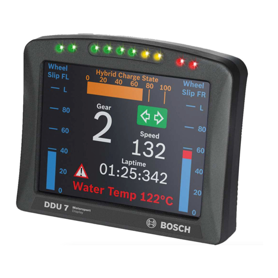
Display Unit DDU 7 Display Configuration | en Configurable LEDs Display area Tabs to switch between different items/ pages Display element configuration 8.2.1 Numeric display element Adding a numeric display element to display page The ‘Large Element’ and the ‘Medium Element’ numeric display elements differ in element and font size. - Page 32 | Display Configuration Display Unit DDU 7 The measurement channel is linked to the numeric display element. Drag + Drop 04.02.2019 | V 02 | Manual Bosch Motorsport...
-
Page 33: Bargraph Display Element
Display Unit DDU 7 Display Configuration | en Configuring a numeric display element Double-click on the numeric display element. The Numeric Wizard window opens. a) Enter the title displayed on top of the numeric display element. b) Enter the text displayed in the middle of the numeric display element. -
Page 34: Alarm' Display Element
| Display Configuration Display Unit DDU 7 a) Enter the title displayed on top of the ‘Bargraph’ display element. b) Choose the measurement channel. c) Define the tick text corresponding with the physical value. You can add more tic labels by entering values in the row labeled with *. - Page 35 Display Unit DDU 7 Display Configuration | en Configuring an ‘Alarm’ (text) display element Double-click on the ‘Alarm’ display element. The Alarm Wizard window opens. a) Enter the title displayed on top of the ‘Alarm’ display element. b) Choose the condition when the alarm will be activated: •...
- Page 36 | Display Configuration Display Unit DDU 7 a) Choose if the alarm can be reset or not. b) Choose if the alarm blinks slowly, fast or does not blink. c) Enter the minimum time the Alarm display element is displayed if an alarm is triggered.
- Page 37 Display Unit DDU 7 Display Configuration | en a) Select the image from the hard drive that is shown in case of an alarm. b) Choose the condition when the alarm will be activated: • Create a condition using the Condition Creator. For more information see chapter ‘Creating a new condition channel’.
-
Page 38: Other Display Elements
| Display Configuration Display Unit DDU 7 Configuring an ‘Alarm Reset Channel’ The Alarm Reset Channel can be defined in the display setting menu. Double click on the display icon in the project tree. On the settings Tab the Alarm Reset Channel can be defined. -
Page 39: Conditional Formatting
Display Unit DDU 7 Display Configuration | en a) Enter the title displayed on top of the Label display element. b) Enter the text displayed in the middle of the Label display element. c) Choose the font size, alignment, borderstyle, background and foreground color of the Label display element. -
Page 40: Context Menu
| Display Configuration Display Unit DDU 7 Double-click on the display element. The Numeric Wizard window opens. Switch to the tab ‘Conditional Formatting’. The lower and the upper limits are configured in the same way. a) Check the box to activate the formatting at a lower limit. -
Page 41: Converting A Gear Channel To Ascii Representation
Choose the measurement channel for ‘Gear’. Gear must have an ASCII quantization (1st gear=‘1’= 49, 2nd gear=‘2’= 50, …). (ASCII quantization is standard for the ‘gear’ channel of Bosch ECUs. If you get the gear information of a different control unit as the Bosch ECU (e.g. a gearbox control unit), use the Gear Lookup Table to translate numeric values to ASCII format. - Page 42 | Display Configuration Display Unit DDU 7 The Gear Lookup Table Wizard appears. Gear Lookup Table Wizard Set up the settings as shown in the screenshot. Click ‘OK’ when done. The ‘Create channel on DDU 8’ window appears. Enter the name and an optional description of the translated ASCII measurement channel.
-
Page 43: Creating Customized Led Pattern
‘Display “on” pattern’ and define the LEDs in the one color. Then choose ‘Display “off” pattern’ and define the LEDs in the other color. Click ‘OK’ when done. The configuration is displayed in the DDU 7 LED Configuration window. 8.3.4 Assigning display pattern priority Assigning display pattern priority You can assign the priority of the created display pattern and shift lights. -
Page 44: Page Select / Display Brightness / Led Brightness
| Display Configuration Display Unit DDU 7 Page select / Display brightness / LED brightness Any “event” can be used to change the display and LED brightness or the display page. Those events can be any input channel or an internal calculated channel. In the following chapters, you will find some examples on how to set up such a configuration. -
Page 45: Option 1: 12 Hardwired Position Switch
Display Unit DDU 7 Display Configuration | en Page 2 is shown with 1.5 <= the value < 2.5 Page 3 is shown with 2.5 <= the value < 3.5 … Page 12 is shown with 11.5 <= the value Brightness switch The brightness can be switched with 6 positions. - Page 46 Voltage = 5000 x R/(R + 3010) 5000: Sensor supply (mV) R: Resistor for each Rotary switch position (Ohm) 3010: Pull-up resistor (Ohm) The following screenshot and the data are an example for a Bosch switch. 04.02.2019 | V 02 | Manual Bosch Motorsport...
- Page 47 Display Unit DDU 7 Display Configuration | en Define minimum and maximum Limit. Select “Output data type” from 8, 16 or 32 Bit. Do not check “Use adjustment value”. Choose the Measurement sheet and click on ‘Finish’. Bosch Motorsport Manual...
- Page 48 | Display Configuration Display Unit DDU 7 Define Name and Description and click on ‘Ok’. 04.02.2019 | V 02 | Manual Bosch Motorsport...
- Page 49 Display Unit DDU 7 Display Configuration | en Click on the ‘Display’ tab and select the ‘Settings’ tab at the bottom. To use the channel as a Page Switch, Select "Channel based" as page switch and select the channel configured above.
-
Page 50: Option 2: Up/Down Switches
Option 2: Up/Down switches Define either one signal for a wrap around switch or two signals for an up/down switch. Select the ‘Display Switch’ and drag it into the DDU 7. Select the Source for signal Up/Down and Edge Falling or Rising. - Page 51 Display Unit DDU 7 Display Configuration | en If you choose “Display switch does not wrap around”, you need two switches to turn the pages in both directions. Define Name and Description and click on ‘Ok’. Bosch Motorsport Manual 04.02.2019 | V 02 |...
- Page 52 | Display Configuration Display Unit DDU 7 In the project tree, select “Display” and then “Open”. To use the channel as a Page Switch, check the box "Use a channel to switch pages" and select the channel configured above.
- Page 53 Display Unit DDU 7 Display Configuration | en In the project tree, select “Download configuration”. If you want to check your configured channel, reassure that the device status is green, double-click on the DDU 10 and select the "Statistics" tab.
-
Page 54: Option 3: Can Input Signal, Math Channel Or Ana_In Channel
| Display Configuration Display Unit DDU 7 8.4.4 Option 3: CAN input signal, math channel or ANA_IN channel Define your CAN, math or analog input channel. Select the 'Display' tab and then the 'Settings' tab at the bottom. 04.02.2019 | V 02 |... - Page 55 Display Unit DDU 7 Display Configuration | en A ‘display settings’ window opens. To use the channel as a brightness switch, check the box "Use a channel to switch brightness" and select the channel configured above. Bosch Motorsport Manual 04.02.2019 | V 02 |...
-
Page 56: Math And Condition Channels
Result can be used as input source for various display elements (numeric elements, alarms, Bargraphs) and further calculations in the whole RaceCon project All math channels can be used globally in the whole DDU 7 project. 8.5.2 Creating a new math channel Follow the steps shown in the screenshot. -
Page 57: Creating A New Conditional Function
Define a value that can be used as a constant in the formula. g) Choose a function. h) Describes the function selected above. Click ‘Finish’ when done. The math channel is displayed in the DDU 7 math channel window. 8.5.3 Creating a new conditional function Follow the steps shown in the screenshot. - Page 58 If-condition changes state from FALSE to TRUE. An example of a condition to set up the maximum front brake pressure is given on the next page. The conditional function is displayed in the DDU 7 math channel window. 04.02.2019 | V 02 | Manual...
-
Page 59: Condition Channels
RaceCon project. Condition combination – Combination of several (up to 16) condition channels for more complex calculations – Logical results All conditions can be used globally in the whole DDU 7 project. Bosch Motorsport Manual 04.02.2019 | V 02 |... -
Page 60: Creating A New Condition Channel
| Display Configuration Display Unit DDU 7 8.6.1 Creating a new condition channel Follow the steps shown in the screenshot. : Double- click on ‘Conditional Channels” in Project Tree : Click on ‘Add condition” The ‚create/edit condition‘ window appears. -
Page 61: Creating A New Condition Combination
Pulse: Result is a short one-time pulse if the condition is fulfilled. Toggling output: Result is a pulse that lasts until the next condition is fulfilled. Click ‘Ok’ when done. The conditional channel is displayed in the DDU 7 condition channel window. 8.6.2 Creating a new condition combination Follow the steps shown in the screenshot. - Page 62 | Display Configuration Display Unit DDU 7 : Double- click on ‘Conditional Channels’ in Project Tree : Click on the dropdown arrow beside ‘Add condition’ : Choose ‘Conditional combination’ The ‚create/edit condition combination‘ window appears. Create/Edit Condition Window Define the condition combination using the following configuration possibilities: a) Enter the name of the condition combination.
-
Page 63: Cpu Load Limits
Logger configuration (total logging rate [kB/s], conditional measurement rates) To help respecting the limit of 85 % CPU load, the DDU 7 creates an error memory entry. To trigger this error entry, the CPU load must exceed the limit for 5 minutes without interruption. -
Page 64: Can Bus
– All devices connected to the bus must use identical data rate Configuration of DDU 7 bus data rate by double click on the CAN bus in project tree (1 MBaud, 500 kBit, 250 kBit, 125 kBit) Row counter concept –... -
Page 65: Can Input
Display Unit DDU 7 CAN Bus | en CAN input 9.2.1 Input configuration 9.2.2 Create new CAN channel Right-click on CAN Input of desired bus (CAN1 or CAN2). Select ‘New CAN Channel’ from menu. Insert name and description of channel. -
Page 66: Can Channel Configuration
| CAN Bus Display Unit DDU 7 9.2.3 CAN channel configuration Extraction of data from CAN bus Mini CAN analyzer functionality Automatic assignment to measurement view Conversion to physical values 9.2.4 Extracting data from CAN bus Representation: Byte Some CAN devices need to be addressed by a byte represented CAN channel. The address can be assigned in this window and is illustrated by a bargraph. -
Page 67: Conversion To Physical Values
CAN analyzer functionality This functionality is only available, if a MSA-Box (I & II) is used to connect the DDU 7 to the PC. Choose the CAN bus that is connected to the MSA-Box to display the raw value and the converted physical value here. -
Page 68: Online View Of Can Channels In Vehicle
The CAN channel can be automatically inserted to a measurement sheet. Insert a name for a new sheet or select an existing sheet from the listbox. For an online view of the value measured by the DDU 7 , insert the channel in an online measurement sheet which is described in the next chapter. -
Page 69: Import A Can Database (Dbc) File
Display Unit DDU 7 CAN Bus | en Drag + Drop The measurement element displays the values of the assigned channel. Connect PC to the vehicle and switch to ‘Race Mode’ by clicking ‘F11’ on the keyboard to display online data. -
Page 70: Import Racecon Can Configuration
| CAN Bus Display Unit DDU 7 Specify the filename. Click ‘OK’ when done. 9.2.10 Import RaceCon CAN configuration Right-click on CAN Input of desired bus (CAN1 or CAN2). Select ‘Import…’ from menu. A file browser opens. Select the input file and click ‘OK’. -
Page 71: Export To Dbc File
Display Unit DDU 7 CAN Bus | en Assign the ambiguous channels to the desired source. Click ‘Finish’. 9.2.11 Export to dbc file Click on this option to save the CAN configuration to a Vector dbc file format. It will open an explorer window where the dbc file can be saved on the harddisc. - Page 72 Click ‘OK’ when done. A CAN message configuration window opens in the Main Area. Click on ‘DDU 7’ in the DDU 7 Project Tree to display all labels. Select the desired measurement channel and drop it on message’s bytes. 04.02.2019 | V 02 |...
- Page 73 Display Unit DDU 7 CAN Bus | en The measurement channel is assigned to the CAN message. A double Click on one of the defined CAN channels opens the following dialogue: In this dialogue additional settings are possible: – Representation: Also a Bitwise CAN signal can be defined. Please define position and length in this case.
-
Page 74: Edit Can Message Multiplexer Settings
| CAN Bus Display Unit DDU 7 9.3.3 Edit CAN Message Multiplexer settings Click “Use multiplexer”, the Option “Hide” opens the multiplexer settings. Representation: Choose Byte or Bit Type of multiplexer Start, Length: Define start position and length of multiplexer (Byte or Bitwise possible) Endianness: Define Byte order (Little Endian –LB, HB, Big Endian –HB, LB) -
Page 75: Import Racecon Can Configuration
Display Unit DDU 7 CAN Bus | en 9.3.5 Import RaceCon CAN configuration Click right on CAN Output of desired bus (CAN1 or CAN2). Select ‘Import…’ from menu. A file browser opens. Select the input file and click ‘OK’. An ‘Import Selection’ window opens. - Page 76 | CAN Bus Display Unit DDU 7 Assign the ambiguous channels to the desired source. Click ‘Finish’. 04.02.2019 | V 02 | Manual Bosch Motorsport...
-
Page 77: Analog And Frequency Inputs
Display Unit DDU 7 Analog and Frequency Inputs | en Analog and Frequency Inputs 10.1 Features 24 analog inputs with Software Upgrade 2; 4 analog inputs without upgrade – 0 … 5 V – 12 bit A/D converter – Switchable 3.01 kOhm pull-up resistor –... -
Page 78: Measurement Channels
Configuring a predefined Bosch sensor with the 'Bosch Sensor Wizard' Click on ‘Measurement Sources’ in the Toolbox. Expand the list of ‘I/O Channels’ by clicking on ‘+’ in the DDU 7 Project Tree. Drag the ‘Bosch Sensor Wizard’ from the Toolbox and drop it on the desired analog input channel in the DDU 7 Project Tree. -
Page 79: Configuring A Generic Linear Sensor
Sensitivity 400 mV/g, Offset 2500 mV The sensor has a linear output signal with sensitivity and offset Click on ‘Measurement Sources’ in the Toolbox. Expand the list of ‘I/O Channels’ by clicking on ‘+’ in the DDU 7 Project Tree. Bosch Motorsport Manual... - Page 80 To activate the internal pullup-resistor, check the box. The internal pullup-resistor is used to get a 5 V signal at the analog channel of the DDU 7. It allows you to use a push-button. The fixed value of the internal pullup-resistor is 3010 Ohm. If using an additional external pullup-resistor, set up the overall resistance.
-
Page 81: Configuring A Generic Non-Linear Sensor
Working with automatically created measurement sheets is explained in chapter ‘Setting up an online measurement, page 97’. Click ‘Finish’ when done. Enter channel name and description. Click ‘OK’ when done. The channel is inserted into the DDU 7 Project Tree. Channel is linked to ANA04 Sensitivity... - Page 82 Wizard’ opens. To activate the internal pull up-resistor, check the box. The DDU 7 pull up-resistor is used to get a 5V signal at the analogue channel of the DDU It allows you to use a push-button. The fixed value of the internal pull up-resistor is 3010 Ohm. If using an additional external pull up-resistor, set up the overall resistance.
- Page 83 Working with automatically created measurement sheets is explained in chapter ‘Setting up an online measurement, page 97’. Click ‘Finish’ when done. Enter channel name and description. Click ‘OK’ when done. The channel is inserted into the DDU 7 Project Tree. Bosch Motorsport Manual 04.02.2019 | V 02 |...
-
Page 84: Configuring A Multipoint Adjustment
A ‘Multipoint Adjustment Wizard’ opens. To activate the internal pullup-resistor, check the box. The internal pullup-resistor is used to get a 5 V signal at the analog channel of the DDU 7. It allows you to use a push-button. The fixed value of the internal pullup-resistor is 3010 ohm. If using an additional external pullup-resistor, set up the overall resistance. - Page 85 Display Unit DDU 7 Analog and Frequency Inputs | en Click ‘Next’ when done. The second part of the ‘Multipoint Adjustment Wizard’ opens. Click ‘Next’ when done. The third part of the ‘Multipoint Adjustment Wizard’ opens. Enter physical limits of the sensor...
-
Page 86: Digital Filter Details
Online definition of the curve is covered in the chapter ‘Online calibration of measurement channels, page 102’ of this manual. 10.3.5 Digital filter details DDU 7 uses A/D converter oversampling and digital filtering to recording rate. Digital filters eliminate ‘out-of-band’ noise 04.02.2019 | V 02 | Manual... -
Page 87: Configuring A Frequency Input
Filtering is (smart) averaging over several samples – Filtered signal is delayed with respect to real time signal – DDU 7 filters have constant, frequency independent delay – Delay (e.g. 22 samples at 10 ms) is corrected during recording –... - Page 88 Display Unit DDU 7 Click ‘Measurement Sources’ in the Toolbox. Expand the list of ‘I/O Channels’ by clicking on ‘+’ in the DDU 7 Project Tree. Drag the ‘Velocity’ digital signal source from the Toolbox and drop it on the desired ‘REV’...
-
Page 89: Computed Sources
Example: Sensitivity/offset calculation on input channel Click ‘Measurement Sources’ in the Toolbox. Drag the ‘Sensitivity/Offset’ computed source from the Toolbox and drop it on ‘Computed Channels’ in the DDU 7 Project Tree. A ‘Computed Sensitivity/Offset Wizard’ opens. Choose input channel... -
Page 90: Hysteresis
97’. Click ‘Finish’ when done. Enter channel name and description. Click ‘OK’ when done. The channel is inserted into the DDU 7 Project Tree. 10.5 Hysteresis The hysteresis function avoids the high-frequent switchover of the measurement channel value. -
Page 91: Special Functionality: Vehicle Speed
Enter name to automatically create a new measurement sheet Click ‘Finish’ when done. Enter channel name and description. Click ‘OK’ when done. The channel is inserted into the DDU 7 Project Tree. Channels available in Computed Calculation of hysteresis Sources... - Page 92 | Analog and Frequency Inputs Display Unit DDU 7 Drag the ‘Speed’ computed source from the Toolbox and drop it on ‘Computed Channels’ in the DDU 7 Project Tree. Do not drop it on ‘DDU 7’! Drag + Drop A ‘Calculated Speed Wizard’ opens.
-
Page 93: Configuring Pwm Outputs
Configuring a PWM output Click on ‘Measurement Sources’ in the Toolbox. Drag the ‘PWM Out’ computed source from the Toolbox and drop it on the desired ‘PWM_OUT’ channel in the DDU 7 Project Tree. A ‘PWM Out Wizard’ opens. Bosch Motorsport Manual 04.02.2019 | V 02 |... - Page 94 The ‘power-on’ state of the PWM output is ‘switch open’ (0% duty cycle). Click ‘Finish’ when done. Enter channel name and description. Click ‘OK’ when done. The channel is inserted into the DDU 7 Project Tree. Channel is linked to Characteristic...
- Page 95 Display Unit DDU 7 Analog and Frequency Inputs | en Measurement label Function pwm_err_ls_out_01_OL PWM output 1 error open load pwm_err_ls_out_01_OT PWM output 1 error over temperature pwm_err_ls_out_01_SCB PWM output 1 error short circuit to battery pwm_err_ls_out_01_SCG PWM output 1 error short circuit to GND Tab. 10.1: Diagnostic channels...
-
Page 96: Online Measurement
– System configuration (channel + display configuration, CAN I/O, PWM Out, etc.) is stored in the DDU 7 – Use RaceCon to create and download configuration from the PC to DDU 7 – Communication interface: Ethernet – Communication protocol: XCP Online measurement + calibration –... -
Page 97: Configuration Download
Display Unit DDU 7 Online Measurement | en A green dot and background at the device in the project view and the DDU 7 Project Tree indicate a successful download and system consistency. If the system’s configuration in RaceCon has been changed, the dot and background becomes yellow and a configuration download is necessary. - Page 98 | Online Measurement Display Unit DDU 7 From the context menu of a measurement page, the folder can be renamed and deleted. It also allows the creation of measurement pages. From the context menu of a measurement page, the page can be renamed and deleted.
- Page 99 Online Measurement | en Drag + Drop Click on ‘DDU 7’ in the Project Tree to display all measurement channels. Select the desired measurement channel and drop it on the measurement element. If the DDU 7 is online, the value is displayed.
-
Page 100: Automatic Creation Of Measurement Sheets
Automatic creation of measurement sheets RaceCon can create measurement sheets automatically. You can create and use measurement sheets with the DDU 7 as well as with all other devices connected to RaceCon. During the configuration of a measurement channel, select a measurement sheet from the list box or enter a name for a new measurement sheet. - Page 101 Click to create measurement sheets The automatically created sheet is inserted in the Project Tree under ‘Measurement Container’ and ‘Device Channels’. If the DDU 7 is connected to RaceCon, live values of the channels are shown. Button for Characteristic online...
-
Page 102: Using The Measurement Sheets
102 en | Online Measurement Display Unit DDU 7 11.2.2 Using the measurement sheets When RaceCon is online, press the ‘F11’ key to switch from ‘Design Mode’ into ‘Race Mode’. The measurement sheet is extended to full screen. The button for offset calibration is active. -
Page 103: Performing The Online Offset Calibration
11.3.2 Performing the online offset calibration DDU 7 has to be connected to RaceCon to calibrate the sensor’s offset. Apply the desired physical condition to the sensor (e.g. 1 G to an acceleration sensor). Open the measurement channel’s online page by double-clicking on the measurement channel name in the Data Area. -
Page 104: Error Memory
Please consider this and replace the product name ‘DDU 8’ in this case with the name of your product. 12.1 Error memory representation in RaceCon Bosch Motorsport devices feature an error memory. Information on errors can be visualized via RaceCon (online measurement) or can be transmitted via telemetry. 12.1.1 Accessing the memory The error memory can be accessed as shown in the illustration: 04.02.2019 | V 02 |... -
Page 105: Clearing The Error Memory
Display Unit DDU 7 Error Memory | en 105 The memory is situated inside the device and is non‐volatile. As a consequence, an error which has occurred and has not been cleared by the user will remain in the error memory even after a power cycle. -
Page 106: Information On Errors Available From The Error Memory
106 en | Error Memory Display Unit DDU 7 12.2 Information on errors available from the error memory In general, properties of the error memory and properties of an individual error need to be distinguished. 12.2.1 Error Memory Properties The following property is available for the error memory itself: –... - Page 107 Display Unit DDU 7 Error Memory | en 107 It is also represented by a color scheme within RaceCon (provided RaceCon is online with the system): 0 (no error present in memory): No orange border MIL off (black) No entries...
-
Page 108: Error Properties
108 en | Error Memory Display Unit DDU 7 2 (at least one active error present in memory): Blinking orange border MIL blinking orange Info cycling through errors present in error memory 12.2.2 Error Properties The following channels are recognized and memorized inside the devices: –... - Page 109 Display Unit DDU 7 Error Memory | en 109 – 0 (FALSE) Error is inactive: error was not detected in most recent diagnostic run, however the error has not been cleared from the memory by the user and remains in the non‐volatile memory...
-
Page 110: Analog Input Diagnosis
110 en | Error Memory Display Unit DDU 7 12.3 Analog Input Diagnosis 12.3.1 Monitoring limits / Shortcut Detection / Cable Breakage The pin diagnosis functionality (check whether measurement is within the desired range) can be activated in the ANA pin setup wizard; to allow for a diagnosis regarding shortcut to ground, shortcut to battery voltage and cable breakage, a minimum / maximum has to be defined. -
Page 111: Open Line Detection
Display Unit DDU 7 Error Memory | en 111 12.3.2 Open Line Detection The implementation of open line detection consists of pull up resistors being activated and deactivated; evaluating the behavior of the measured value detects cable breakage, regardless of the pull up resistor being activated by the user. -
Page 112: Recording And Telemetry
Programmable IP configuration – BT 60 diagnosis via DDU 7 13.2 Configuration of recordings Expand the list of ‘Loggers’ by clicking on ‘+’ in the DDU 7 Project Tree. Double-click to display the configuration (automatically change to "Logger" Double-click on ‘Recording’ in DDU 7 Project Tree. The recording configuration is displayed in the Main Area. - Page 113 Variables can be grouped Tabs to access conditions, settings and statistics To add measurement channels to a recording, click ‘DDU 7’ in the DDU 7 Project Tree. In the Data Area, the measurement channels are displayed. Drag and drop desired measurement channels into recording group.
-
Page 114: Adding A Recording
Adding a recording DDU 7 supports up to two independent recordings. To add a recording, select ‘Add Recording’ from the context menu of the Logger in the DDU 7 Project Tree. Maximum two recordings are possible. In the device software the 2nd recording is reserved for scruteneering data. -
Page 115: Recording Statistics
The overview helps to detect bandwidth bottlenecks of channels. Bandwidth bottlenecks can be solved by changing the ‘fast/slow block’ setting for each channel. The data rate of the whole system is often less than the data rate of the DDU 7 and limits the overall transmission speed. -
Page 116: Recording Diagnosis
116 en | Recording and Telemetry Display Unit DDU 7 13.2.5 Recording diagnosis The channel ‘statectrl_ok’ of the DDU 7 can be used for online monitoring of recording status. Value Name RECORD DATAOK BLKOK STARTED Content of status bits Name... -
Page 117: Displaying Online Recording Diagnosis ('Statectrl_Ok')
0, a red highlighted channel means 1. – Measurement correctly initialized, but recording threshold(s) not reached: 254 – Measurement correctly initialized, DDU 7 is recording data: 255 – Values less than 254 indicate an error state –... -
Page 118: Hardware Setup
118 en | Recording and Telemetry Display Unit DDU 7 Link quality at Hockenheim 13.3.2 Hardware setup 13.3.3 Software setup Drop FM 40 from Toolbox into system overview. 04.02.2019 | V 02 | Manual Bosch Motorsport... - Page 119 5 % recommended for improved re-syncronization Adding channels to telemetry Expand the list of ‘Loggers’ by clicking on ‘+’ in the DDU 7 Project Tree. Double-click on ‘Recording’ in DDU 7 Project Tree. The recording configuration is displayed in the Main Area.
-
Page 120: Telemetry Channels With Special Functionality
120 en | Recording and Telemetry Display Unit DDU 7 None: Channels are not transferred Slow: Channels are transferred into the slow telemetry block Fast: Channels are transferred into the fast telemetry block 13.3.4 Telemetry channels with special functionality The FM 40 allows the transmission of special information such as running distance of current lap, lap number of current lap and lap time, fuel consumption of last lap completed. -
Page 121: Setup For Usb Recording
Display Unit DDU 7 Recording and Telemetry | en 121 Click ‘Edit channel(s)’. An ‘Edit Telemetry Channel’ window appears. Choose the channel type. The table below shows the function of the available channel types. Measurement channel Function Lap time Exact lap time of lap completed... -
Page 122: Recording Data On Usb Device
Power on the system and connect with RaceCon to the vehicle. Download the configuration to the DDU 7. Record measurement data. If an USB device is present, the DDU 7 stores the data in parallel on the internal memory and the USB device. - Page 123 Display Unit DDU 7 Recording and Telemetry | en 123 Click on the ‘Import/Export’ icon. 10. Select ‘Data logger CXX/DDUX/MSX and click ‘OK’ when done. The ‘Read measurement data’ dialog opens. Click 'read data from logging device' 11. Click on ‘Settings’ tab and select the option ‘Flash Card/USB Stick’.
- Page 124 124 en | Recording and Telemetry Display Unit DDU 7 13. Click ‘Close’ when transmission has finished. 14. Click on the Start button and choose ‘Open measurement file’. 15. Select the measurement files from the storage folder. 16. Click on ‘Open’.
- Page 125 DDU 7 still records data. If the USB device is unplugged and re-inserted for > 4 s while the DDU 7 is powered up or a different USB device is plugged in, the DDU 7 restarts. In this case, the DDU 7 is not operational for 1.5 s.
-
Page 126: Usb Device Handling Hints
DDU 7 still records data. If the USB device is unplugged and re-inserted for > 4 s while the DDU 7 is powered up or a different USB device is plugged in, the DDU 7 restarts. In this case, the DDU 7 is not operational for 1.5 s. -
Page 127: Lap Trigger
Receiver (in-vehicle unit) Lap Trigger Transmitter Lap Trigger Receiver 14.1.1 Electrical trigger signal In DDU 7 all sources of measurement channels can be used as trigger signal. – Analog input – Digital input – CAN input Signal (measurement channel) properties Low active signal (Bosch triggers): Trigger releases if signal is below the threshold. -
Page 128: Prevention Of False Triggers
128 en | Lap Trigger Display Unit DDU 7 – Sub‐trigger (segment time, optional, not applicable with GPS lap trigger) Bosch standard: – Main trigger 20 ms, low active (Recommendation for RaceCon “Detecion Time” setting: 15 ms, Setting must be a slightly shorter period than the signal length of the trigger to avoid a missed trigger due to the update rate) –... - Page 129 Enter the distance of the racetrack Notice! In this example, the Rx is connected to the dedicated lap trigger pin of DDU 7. The channel ‘speed’ is calculated from 4 wheel speeds. Click ‘Finish’ to complete the operation. A pre-configured lap trigger window opens.
-
Page 130: Lap Trigger Channel Diagnosis/Counter Reset
130 en | Lap Trigger Display Unit DDU 7 14.1.5 Lap trigger channel diagnosis/counter reset To display a quick lap trigger channel diagnosis and to reset counters use the diagnosis page in RaceCon. Any ‘Laptrigger_xxx’ channel can be displayed. Double-click on any ‘Laptrigger_xxx’ channel in the Data Area. Example: ‘laptrigger_lapdist_dls’... -
Page 131: Counting Outing/Laps/Fragments
Display Unit DDU 7 Lap Trigger | en 131 14.2 Counting outing/laps/fragments Functionality – Power ON: system + measurement is initialized but not yet started – Global start condition fulfilled: recording starts – Reception of valid lap trigger: recording of lap completed, new lap starts –... -
Page 132: Lap Timing
132 en | Lap Trigger Display Unit DDU 7 14.3 Lap timing There are different possibilities to adjust the lap trigger to the timing situation. The detection time defines the minimum time the input signal changes its state. E.g. a low active signal needs to be below the threshold for min. -
Page 133: Distance Based Forced Trigger
Display Unit DDU 7 Lap Trigger | en 133 To deactivate distance based retrigger protection, set min distance to 0%. 800m Main Trigger 14.3.3 Distance Based Forced Trigger After a missed main trigger, a forced trigger is inserted, if 120% of the track distance has been covered (4,800 m). -
Page 134: Segment Timing
134 en | Lap Trigger Display Unit DDU 7 14.4 Segment timing Segment timing is the calculation of elapsed time for parts of laps (segments). Segments are defined: – based on sub-trigger signals (additional transmitters) – based on distance travelled Times for segments are compared to: –... -
Page 135: Distance Mode
Display Unit DDU 7 Lap Trigger | en 135 Sub Trigger Trigger Sub Trigger Main Trigger The sub trigger mode cannot be used with the GPS lap trigger. 14.4.2 Distance Mode Using main trigger (20 ms pulse) at Start-Finish-Line. Set ‘Mode’ to ‘Distance’ and enter desired segment distances. -
Page 136: Countdown Timer
136 en | Lap Trigger Display Unit DDU 7 14.5 Countdown timer Some race classes require a minimum time spent in the pits. An additional lap trigger Tx is configured as a segment trigger positioned at pit entry. The trigger signal starts a timer countdown. -
Page 137: Firmware
Calibration data: Characteristic curves and offsets created by online calibration at the vehicle. Recorded data: Measurement data recorded during vehicle operation. 15.2 Firmware update The scheme shows the process during each connection between RaceCon and DDU 7. RaceCon DDU 8 Firmware version... - Page 138 138 en | Firmware Display Unit DDU 7 In the DDU 7 Project Tree, right-click on ‘DDU 7’ and choose ‘Synchronize’ then ‘Update firmware’. A pop-up menu opens. Select the destination of the firmware archive (PST). Click ‘OK’ when done.
- Page 139 Display Unit DDU 7 Firmware | en 139 Bosch Motorsport Manual 04.02.2019 | V 02 |...
-
Page 140: Clone The Unit
140 en | Clone the Unit Display Unit DDU 7 Clone the Unit To replace a DDU 7 by another device, it is possible to clone it. A clone is a 1:1 copy of a device. Create a clone file: Click ‘Clone extract’... - Page 141 Display Unit DDU 7 Clone the Unit | en 141 – Upgrade features Bosch Motorsport Manual 04.02.2019 | V 02 |...
-
Page 142: Gps Sensor
Baud rate: 9,600 is standard for GPS, DDU 7 supports 1,200 to 115,200 baud. GPS Rx interface baud rate must match DDU 7 interface baud rate. DDU 7 Baud rate can be set with the ‘GPS_BAUDRATE’ characteristic Data format: DDU 7 expects 8 data bits, no parity bit, 1 stop bit (8N1) 17.2... -
Page 143: Gps Troubleshooting
DDU 7? Is the GPS sensor powered up? Does the GPS sensor deliver RS232 signal levels? Interface Do the baud rates of the GPS sensor and the DDU 7 match? Bosch Motorsport Manual 04.02.2019 | V 02 |... - Page 144 Is the GPS sensor set up for 8N1 transmission parameters? Is the GPS sensor set up for NMEA messages? Are the GGA, VTG, RMC messages activated? Is Software Upgrade 2 activated in the DDU 7? GPS sensor start-up Does the GPS sensor ‘view’ the sky? Did the GPS sensor complete its initial start-up procedure? This may take up to 20 min.
-
Page 145: Fuel Consumption Calculation
Display Unit DDU 7 Fuel Consumption Calculation | en 145 Fuel Consumption Calculation 18.1 Setting up fuel consumption calculation and tank management Select ‘Measurement Sources’ in Toolbox. Drag ‘Fuel’ element and drop it on the vehicle in System Overview. Do not drop it on the... -
Page 146: Fuel Consumption Diagnosis/Counter Reset
146 en | Fuel Consumption Calculation Display Unit DDU 7 a) Change device for fuel calculation, if desired. b) Enter tank capacity of vehicle. c) Choose calculation mode: • using fuel consumed (summed-up fuel consumption) • using fuel flow rate (momentary fuel consumption) d) Choose input channel and enter adaption factor. -
Page 147: Example
Display Unit DDU 7 Fuel Consumption Calculation | en 147 Button to reset total fuel consumption (Reset with RaceCon only) Button to reset fuel consumption manually (Can also be Settings triggered ‘by signal overview source’ or ‘on power down’) 18.3... -
Page 148: Enhancements
148 en | Enhancements Display Unit DDU 7 Enhancements 19.1 Modular sensor interface M 60 Up to eight M 60 modules can be used for I/O expansion in a network. 19.1.1 Technical data The M 60 is a compact and light weight sensor interface unit for analog and digital sensors. Up to eight M 60 can be used to expand the number of input channels of the data logger C 60 as well as the display DDU 9. - Page 149 Display Unit DDU 7 Enhancements | en 149 3-port network switch RS232 GPS input CCP-Master, data acquisition from ECU that support CAN calibration protocol (optional) Mechanical Data Size 105 x 34.5 x 137.5 mm Weight 495 g Operating temperature -20 to 65°C Max.
-
Page 150: Assign The Mounting Location
150 en | Enhancements Display Unit DDU 7 19.1.2 Assign the mounting location The mounting location is used for determination between the different M 60. Following position definitions are possible: Front, Rear, Center, Gearbox, Front Left, Front Right, Rear Left, Rear Right At delivery no mounting location is set. - Page 151 Display Unit DDU 7 Enhancements | en 151 Compare the listed device Type, F-Number and Serial Number to the identification plate to identify the device you want to make changes to: Assign the desired mounting location (e.g. ‘Front’) and confirm by clicking ‘Apply’...
- Page 152 152 en | Enhancements Display Unit DDU 7 The mounting location is now stored in the device. The device will do a reset and the ‘RUN’ led on the device will change to green. The list will show the new mounting location assignment.
-
Page 153: Feature Activation
Display Unit DDU 7 Enhancements | en 153 19.1.3 Feature activation Please follow the instructions of the DDU Feature activation also for the M 60 (see chapter ‘Feature activation’). Bosch Motorsport Manual 04.02.2019 | V 02 |... -
Page 154: Racecon Shortcuts
154 en | RaceCon Shortcuts Display Unit DDU 7 RaceCon Shortcuts The table shows important shortcuts simplify controlling the DDU 7 in RaceCon. Shortcut Function General navigation Open RaceCon help Rename selected object Select Data Area Select Project Tree –... - Page 156 Bosch Engineering GmbH Motorsport Robert-Bosch-Allee 1 74232 Abstatt Germany www.bosch-motorsport.com © Bosch Engineering GmbH, 2018...
Need help?
Do you have a question about the DDU 7 and is the answer not in the manual?
Questions and answers