Table of Contents
Advertisement
Model Series 5000E - 1/2 HP
Model Series 2000E - 1/3 HP
CAUTION! PLEASE READ THIS MANUAL CAREFULLY!
The MODEL NUMBER label is located on the front panel of your opener.
CONTENTS
Safety Rules .....................................................................2
Features of Your Opener..................................................3
Specifications ...................................................................3
You'll Need Tools .............................................................3
Completed Installation Illustration ....................................4
Operation of Your Opener ................................................5
Accessories ......................................................................5
Care & Maintenance of Your Opener ...............................6
Assembly Instructions ......................................................7
Installation Instructions ...................................................10
Travel Limit Adjustments ................................................20
FASTEN THIS MANUAL NEAR THE GARAGE DOOR AFTER INSTALLATION.
PERIODIC CHECKS OF THE OPENER ARE REQUIRED TO INSURE SATISFACTORY OPERATION.
Garage Door Opener
Owner's Manual
FOR RESIDENTIAL USE ONLY
PAGE
The Chamberlain Group, Inc.
845 Larch Avenue
Elmhurst, Illinois 60126-1196
Model Series 4000E - 1/2 HP
Model Series 1000E - 1/4 HP
CONTENTS
Force Adjustments .........................................................21
Safety Reverse Test .......................................................22
The Protector System™ .................................................22
Code Programming Instructions .....................................23
Having a Problem? ...................................................24, 25
Carton Contents & Hardware Illustrated.........................26
Repair Parts, Rail Assembly...........................................26
Repair Parts, Installation ................................................26
Repair Parts, Opener Assembly .....................................27
How To Order Repair Parts ............................................28
Warranty .........................................................................28
PAGE
Advertisement
Table of Contents

Subscribe to Our Youtube Channel
Related Manuals for Chamberlain Series 1000E


Summary of Contents for Chamberlain Series 1000E
-
Page 1: Table Of Contents
Repair Parts, Installation ...26 Repair Parts, Opener Assembly ...27 How To Order Repair Parts ...28 Warranty ...28 The Chamberlain Group, Inc. 845 Larch Avenue Elmhurst, Illinois 60126-1196 Model Series 4000E - 1/2 HP Model Series 1000E - 1/4 HP PAGE... -
Page 2: Safety Rules
Start By Reading These Important Safety Rules THESE SAFETY ALERT SYMBOLS MEAN CAUTION - PERSONAL SAFETY, PROPERTY DAMAGE OR DANGER FROM ELECTRIC SHOCK. READ THESE INSTRUCTIONS CAREFULLY. THIS GARAGE DOOR OPENER IS DESIGNED AND TESTED TO OFFER REASONABLY SAFE SERVICE PROVIDED IT IS INSTALLED AND OPERATED IN STRICT ACCORDANCE WITH THE FOLLOWING SAFETY INSTRUCTIONS. -
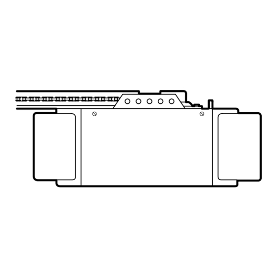
Page 3: Features Of Your Opener
Before you begin, please check the contents of the cartons. Illustrations of parts and hardware are shown on pages 26 and 27. Separate the hardware for assembly and installation as shown. FEATURES OF YOUR OPENER 1. Opener Light(s): Turns on and off automatically with 4-1/2 minute illumination for your safety and convenience. -
Page 4: Sectional Door
BEFORE YOU BEGIN, PLEASE TAKE SOME TIME TO CAREFULLY EXAMINE THE ILLUSTRATIONS OF A TYPICAL GARAGE DOOR OPENER INSTALLATION ON BOTH A SECTIONAL AND A ONE-PIECE DOOR. Some installation instructions vary for sectional and one-piece doors. Follow only those instructions which apply to your door type. -
Page 5: Operation Of Your Opener
Operation of Your Opener • BEFORE YOU PROCEED, PLEASE READ SAFETY RULES ON PAGE 2 AND THE OPERATING INSTRUCTIONS ON THIS PAGE CAREFULLY. • DO NOT PERMIT CHILDREN TO PLAY IN THE AREA OF THE DOOR. TO ACTIVATE THE OPENER Use any of the following devices: 1. -
Page 6: Care & Maintenance Of Your Opener
When properly installed on a door which is in balance and in good repair, opener will provide high performance with a minimum of maintenance. The opener does not require additional lubrication. Most complaints of unsatisfactory opener operation can be traced to problems with the door itself. When operated manually, a properly balanced door will stay in any point of travel while being supported entirely by its springs. -
Page 7: Assembly Step
Assembly Step 1 5/16 -18x7/8 Assemble T-rail and Attach Cable Pulley Bracket Cable Pulley Bracket • Place the 4 T-rail sections on a flat surface for assembly. Center sections are interchangeable. Front and back sections are also interchangeable for ease of assembly. Lock Washer •... - Page 8 Assembly Step 2 Assemble and Install Trolley AS A TEMPORARY STOP, INSERT A SCREW- DRIVER INTO HOLE IN FRONT END OF T-RAIL. Attach threaded shaft to trolley with lock washer and nuts as shown. Outer Nut Trolley Temporary Stop Screwdriver Assembly Step 3 Fasten T-rail to Opener PROCEDURE: Place the opener on packing...
-
Page 9: Install Chain/Cable And Attach Sprocket Cover
Assembly Step 4 Install Chain/Cable and Attach Sprocket Cover Detach cable loop from carton and fasten to flat end of trolley with a master link from coin envelope. MASTER LINK PROCEDURE: Push pins of master link bar through cable loop and hole in front end of trolley. -
Page 10: Installation Step
Installation Step 1 Determine Header Bracket Location Installation procedures vary according to garage door types. Follow the instructions which apply to your door. IF YOURS IS A CANOPY OR DUAL-TRACK STYLE GARAGE DOOR, A DOOR ARM CONVERSION KIT IS REQUIRED. FOLLOW THE INSTALLATION INSTRUCTIONS INCLUDED WITH THE REPLACEMENT DOOR ARM. -
Page 11: One-Piece Door Without Track
ONE-PIECE DOOR WITHOUT TRACK Please read and comply with the warnings on page 10. They apply to the installation of the header bracket regardless of door type. • Close the door and mark the inside vertical centerline of your garage door. Extend the line onto the header wall above door. -
Page 12: Attach T-Rail To Header Bracket
Installation Step 2 Install the Header Bracket & Attach T-rail To Header Bracket (All Door Types) FASTEN THE HEADER BRACKET TO THE WALL • Center the bracket on the vertical guideline with the bottom edge of the bracket on the horizontal line as shown (with the arrow pointing toward the ceiling). -
Page 13: Hang The Opener
Installation Step 3 Position the Opener Follow instructions which apply to your door type as illustrated. SECTIONAL DOOR & 1-PIECE DOOR WITH TRACK NOTE: A 25mm board is convenient for setting an ideal door-to-T-rail distance. It is not necessary when headroom is insufficient. PROCEDURE: Raise the opener onto a stepladder. - Page 14 Press again to REVERSE door during the CLOSING cycle or to STOP door during OPENING cycle. INSTALL LIGHT (Models 4000E, 2000E & 1000E): Install a 75 watt maximum light bulb in socket as shown. Light will turn on and remain lit for 4-1/2 minutes when power is connected.
- Page 15 Install Multi-Function Door Control Panel (Model 5000E Only) • Remove about 6mm of insulation from both ends of 2- strand bell wire. Connect one end to terminal screws on back of multi-function door control panel as follows: white/red to terminal screw 1 and white to terminal screw 2.
-
Page 16: Permanent Wiring Connection
Installation Step 6 Attach Manual Release Rope & Handle Trolley Release Arm Rope Overhand Knot Installation Step 7 Connect Electric Power Opener MUST be permanently wired or plugged into a grounded 3-prong receptacle wired according to local electrical codes. DO NOT use a 2-wire adapter. DO NOT USE an extension cord. -
Page 17: Fasten Door Bracket
Installation Step 8 Fasten Door Bracket Follow instructions which apply to your door type as illustrated below. IF YOURS IS A CANOPY OR DUAL-TRACK STYLE GARAGE DOOR, A DOOR ARM CONVERSION KIT IS REQUIRED. FOLLOW THE INSTALLATION INSTRUCTIONS INCLUDED WITH THE REPLACEMENT DOOR ARM. EXERCISE CARE IN REMOVING AND ASSEMBLING ARM CONVERSION KIT. -
Page 18: Connect Door Arm To Trolley
Installation Step 9 Connect Door Arm to Trolley Follow only those instructions which apply to your door type. Make sure garage door is closed tight. Pull the manual release handle to disconnect the trolley. Manually move outer trolley back to the center of inner trolley as shown in Figures A, B and C. FIGURE A: Fasten straight door arm section to outer trolley with the 5/16"x1"... -
Page 19: One-Piece Doors
ASSEMBLE DOOR ARM: Fasten straight and curved door arm sections together to their longest possible length. With door closed, connect straight door arm section to door bracket with the 5/16"x1-1/4" clevis pin. Secure with a ring fastener. Before connecting door arm to trolley, limits of travel must be adjusted on one-piece doors. Limit adjustment screws are located on left side panel as shown in illustration on page 20. -
Page 20: Travel Limit Adjustments
Adjustment Step 1 Adjust UP and DOWN Limits LIMIT ADJUSTMENT settings regulate the points at which the door will stop when moving up or down. NOTE: Door STOPS in the UP direction if anything interferes with door travel. Door REVERSES in the DOWN direction if anything interferes with the door travel (including binding or unbalanced doors). -
Page 21: Force Adjustments
Adjustment Step 2 Adjust Force Force Adjustment Controls are located on back panel of opener. FORCE ADJUSTMENT settings regulate amount of the power required to open and close door. NOTE: The door STOPS in the UP direction if anything interferes with its travel. Door REVERSES in the DOWN direction if anything interferes with its travel (including binding or unbalanced doors). -
Page 22: Safety Reverse Test
Adjustment Step 3 Test Safety Reverse System PROCEDURE: Place a 25mm obstacle on the floor under the garage door. Operate door in DOWN direction. The door MUST reverse on the obstruction. If the door STOPS on the obstruction, it is not traveling far enough in the DOWN direction. -
Page 23: Code Programming Instructions
Code Programming Instructions Manufactured under 1 or more of the following U.S. patents: RE29,525; 4,037,201; 4,750,118; 4,806,930. Other Patents Pending Your garage door opener receiver and remote control transmitter has been set at the factory to a matching code. The door will open when the button on the remote is pressed. Below are instructions for programming any additional remotes you may purchase. -
Page 24: Having A Problem
Having a Problem? Situation OPENER DOESN’T OPERATE FROM EITHER THE REMOTE CONTROL TRANSMITTER OR THE DOOR CONTROL OPENER OPERATES FROM REMOTE CONTROL BUT NOT FROM DOOR CONTROL DOOR OPERATES FROM DOOR CONTROL BUT NOT FROM REMOTE CONTROL TRANSMITTER REMOTE CONTROL HAS SHORT RANGE THE GARAGE DOOR OPENS AND CLOSES BY ITSELF... - Page 25 Having a Problem? Situation DOOR REVERSES FOR NO APPARENT REASON OPENER LIGHT OPENER STRAINS OR MAXIMUM FORCE IS NEEDED TO OPERATE DOOR OPENER MOTOR HUMS BRIEFLY, THEN WON'T WORK OPENER WON'T OPERATE DUE TO POWER FAILURE CHAIN DROOPS OR SAGS OPENER NOISE IS DISTURBING IN LIVING QUARTERS OF HOME...
-
Page 26: Carton Contents & Hardware Illustrated
Repair Parts Separate all hardware for assembly and installation procedures as shown below. ASSEMBLY HARDWARE Rail Assembly Hardware Kit #41A2848 Hex Screw Washered Screw 5/16"-18x7/8" (3) 5/16"-18x1/2" (2) (mounted in opener) Lock Washer 5/16" (4) Master Link (2) 5/16"-18 (5) Carriage Bolts Lock Nut 1/4"-20x1/2"... -
Page 27: Opener Assembly Parts
OPENER ASSEMBLY PARTS (Series 5000E) (Series 4000E, 2000E & 1000E) (Down) LIMIT SWITCH ASSY. Contact Brown wire Grey wire Drive Gear Center Limit (Up) Yellow Contact Contact Wire PART DESCRIPTION 31D380 Sprocket cover 41C4220A Gear and sprocket assembly Complete with: Spring washer,... -
Page 28: How To Order Repair Parts
CHAMBERLAIN GARAGE DOOR OPENER ONE-YEAR LIMITED WARRANTY The Chamberlain Group warrants to the first retail purchaser of this product that it will be free from any defect in materials and/or workmanship for a period of twelve full months from the date of purchase. The product must be used in complete accordance with Chamberlain's instructions for installation, operation and care.
Need help?
Do you have a question about the Series 1000E and is the answer not in the manual?
Questions and answers