Table of Contents
Advertisement
Quick Links
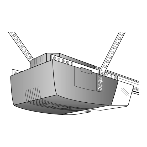
Model 1000SD
Please read this manual and the enclosed safety materials carefully!
Fasten the manual near the garage door after installation.
The door WILL NOT CLOSE unless the Protector System
aligned.
Periodic checks of the opener are required to ensure safe operation.
The model number label is located on the back of your opener.
Garage Door Opener
Owner's Manual
1/3 HP
For Residential Use Only
The Chamberlain Group, Inc.
A DUCHOSSOIS ENTERPRISE
TM
845 Larch Avenue
Elmhurst, Illinois 60126-1196
Complies with UL 325
regulations effective
January 1, 1993
Model 2000SD
1/2 HP
®
is connected and properly
®
Advertisement
Table of Contents


Need help?
Do you have a question about the 1000SD and is the answer not in the manual?
Questions and answers