
Related Manuals for Santint MS3


Summary of Contents for Santint MS3
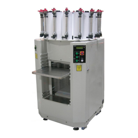
- Page 1 MS3 Manual Dispenser & Automatic Shaker MANUAL ISO 9001: 2000 CERTIFIED CE CERTIFIED Please read this manual carefully before operation.
-
Page 2: Table Of Contents
Table of Contents Chapter Page No. Table of Contents Preface General Safety Instructions Configuration Technical Parameters Installation Preparations before Operation Operation Dispensing Maintenance 10.0 Replacement 11.0 Frequent Issues and Troubleshooting 12.0 Circuit Diagram 14.0 Explosion Diagram 15.0 Nameplate - 1 -... -
Page 3: Preface
5. Unplug the MS3 if it is not in use for extended periods of time. 6. When the MS3 needs to be transported to a new site, please secure it by re-inserting the steel rod through the base and re-install the four feet clamps. The turntable must be locked by the locking pole so that it is secure. - Page 4 10. Surrounding temperature:5℃-50℃; Relative humidity: 15%-90%; 11. Max altitude ≤1000 m. 12. Prior to any maintenance, please unplug the MS3. 13. Use a forklift to gently move the MS3 to the desired location. (see Figure 2.2) (Figure 2.2) - 3 -...
-
Page 5: Configuration
Configuration Please See Figure 3.1 as below: (Figure 3.1) - 4 -... -
Page 6: Technical Parameters
4. To move the MS3, raise the feet by turning them in an anti-clockwise (see Figure 5.2) . 5. Once the MS3 is moved to its final location (must be a flat hard surface), turn the feet in the clockwise direction until all 4 feet are touching the ground and the MS3 is secure and stable.. -
Page 7: Preparations Before Operation
(Figure 5.2) (Figure 5.3) (Figure 5.4) (Figure 6.1) (Figure 6.2) Preparations before Operation In order to ensure that the shaker works well, please refer to the following preparations below: 1. Identification on Control Panel (see Figure 6.1 and 6.2) Figure: “Shaking” mode engaged when T1, T2, or T3 is pressed. - 6 -... - Page 8 Figure: "Shaking" T1 Button—T1 Seconds Button: once pressed, the clamping plate will automatically clamp the paint can and shake the paint can for T1 seconds; T2 Button—T2 Seconds Button: once pressed, the clamping plate will automatically clamp the paint can and shake the paint can for T2 seconds; T3 Button—T3 Seconds Button: once pressed, the clamping plate will automatically clamp the paint can and shake the paint can for T3 seconds.
-
Page 9: Operation
3) Before operation, remove the air out of each pump. Follow the procedures:: ● Press and hold the Rough release button and pull the Rough gauge upwards to a certain height, ie. 1Y. ● Release the Rough release button back to its original position ●... -
Page 10: Dispensing
o Move the turntable to the left and right slightly to let the brake handle return to its original position. o The turntable is now locked. 2. Shaking Switch the mains switch to the “ON” position. The shaker will automatically initialize and the LCD will display “Initializing”. - Page 11 Dispensing Procedures: 01 Determine the dispensing quantity of different colorant as per the formula. 02 Put an open base paint can on the shelf, pull the turntable brake handle down into the horizontal slot, and rotate the turntable until the nozzle is right above the base paint can.
-
Page 12: Maintenance
when falling freely to the zero-scale. ● Set the Rough or Fine gauge to zero-scale when it is not in use. ● The aggregation of the shots by black and red gauges should be equal to the dispensing quantity specified in the formula. 08 Use the same method to dispense all the other required colorant into the base paint can. - Page 13 03 Set the black gauge at its full scale; lift up the plunger handle to check if the shaft is stuck by colorant. If yes, the big piston must be replaced because it has been worn out and/or broken. 3)Periodical Maintenance The dispenser must be maintained every 3-6 months: 01 Check to see if the fixed base is loose or not (Figure 9.2A).
-
Page 14: Replacement
04. Properly dispose the mix of cleaner and colorant according to local environmental regulations. 05. Reinstall the canister on the turntable. 06. Add some cleaner into the canister. 07. Set the Rough gauge to its maximum scale. 08. Put a container right below the nozzle and then operate as dispensing procedures (6.3). -
Page 15: Frequent Issues And Troubleshooting
11.0 Frequent Issues and Troubleshooting For issues not listed, please contact us. Troubles Diagnoses Troubleshooting Motor doesn’t work Power supply does Check if the Mains Switch is with charge, engage. the plug is plugged well. The fuse is broken. Replace fuse. The wire to the motor is not Open the top cover plate, reconnect the connected. - Page 16 Check if the Mains Switch is with charge, Power supply is not working. the plug is plugged well and the mains switch is “ON” position. LCD has no display The fuse or the power supply Replace the fuse or power cord. cord is broken.
- Page 17 The shaker is not leveled. Adjust the feet to level. During shaking, shaker’s noise vibrations increase. The paint can is deformed. Replace with a normal paint can. Overloaded Decrease load. After the paint can is clamped, still displays “shaking” and the Flip the switch in the capacitor box mounted second counter is counting Start-up capacitor is broken.
-
Page 18: Circuit Diagram
12.0 Circuit Diagram Insert the electric circuit diagram - 17 -... -
Page 19: Explosion Diagram
13.0 Explosion Diagram Explosion Diagram of Shell: Name Name Triangle Belt Motor for Mixing Motor Wheel Circuit Board for Display - 18 -... - Page 20 Explosion Diagram of Inner Frame Assembly Name Name DC Motor for Clamping Synchronized Belt Clamping Plate Principal Axis Assembly Bearing Base for Loading Plate - 19 -...
- Page 21 Explosion Diagram of Middle Frame Assembly Name V Triangle Belt DC Motor - 20 -...
- Page 22 Explosion Diagram of Base Frame Assembly Name Shock Absorption Assembly - 21 -...
- Page 23 Explosion Diagram of Shock Absorption Assembly Name Washer - 22 -...
- Page 24 Explosion Diagram of Principal Axis Assembly Name UCP206 Bearing - 23 -...
- Page 25 Name Main Circuit Board - 24 -...
- Page 26 Explosion Diagram of Assembly of Piston Kit Name Name Screw (M4x10) Large Piston Plunger Handle Large Piston Wiper Screw (M4x10) Circlip for Shaft Red Gauge (Fine Gauge) Small Piston Shaft Small Piston Shaft Fixed Base Assembly Small Piston Set Screw (M4x6) Small Piston Head Active Base Assembly Large Piston Head...
- Page 27 Explosion Diagram of Assembly of Canister Name Name Canister Lid Canister Collar Pin Crankshaft Agitator Tapping Screw Shaft Bushing of Agitator - 26 -...
- Page 28 Explosion Diagram of Assembly of Canister/Pump Name Name Bolt(M4X10) Sniff-Back Piston Piston Kit Gauge Rubber Cover, Wiper Pump Assembly Wiper Valve Assembly Pan-Head Screw(M3X16) O-ring(8X1.8) Vale Handle Nozzle Torsion Spring O-ring(7.2X1.8) O-ring(16X1.8) Washer Fixing Nut, Linking Block Vale Pole Canister Kit O-ring(3.15X1.8)...
- Page 29 Explosion Diagram of Assembly of Turntable Name Name Protection Cap Rotary Shaft Stelliform Plate Principle Axis Wheel Plastic Sleeve Bearing Base Plastic Washer Support Eccentric Shaft Base Stopper Big Nut Bearing Stop Washer Turntable Big Plastic Washer Shore - 28 -...
-
Page 30: Nameplate
14.0 Nameplate Name plate - 29 -... - Page 31 ZHENGZHOU SANHUA TECHNOLOGY & INDUSTRY CO., LTD. Address: Xushui Industrial & Trading Park, Zhongyuan West Road, Zhengzhou, Henan Province, P. R. China Postcode: 450042 Tel:0371—65110760,800-8836987 / Fax:0371-67857219 website: www.santint.com e-mail: info@santint.com...
Need help?
Do you have a question about the MS3 and is the answer not in the manual?
Questions and answers