
Related Manuals for LINDR PYGMY 30/K profi


Summary of Contents for LINDR PYGMY 30/K profi
- Page 1 INSTRUCTION MANUAL LINDR FLOW-THROUGH CONTACT COOLER ENGLISH Number 012-2020 REV00 Valid 2020-06-01...
- Page 2 Read this manual carefully before installing and using the device. It contains important information necessary to ensure that all operations are done prop- erly and safely. is manual is a translation of the original Czech manual. LINDR.CZ s.r.o. Sadová 132 503 15 Nechanice, Czech Republic mobile: + 420 775 715 494 tel.:+420 495 447 239...
-
Page 3: Table Of Contents
Contents: Introduction ........Description of the cooler . -
Page 4: Introduction
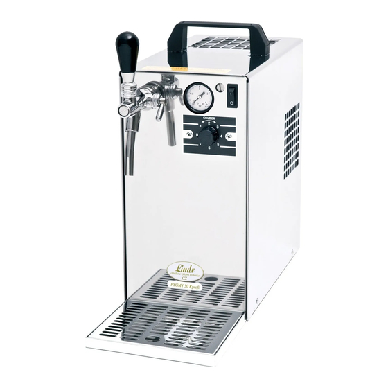
1. INTRODUCTION: ered impermissible and therefore dangerous. The supplier is not liable for damage caused Thank you for purchasing this LINDR product. by incorrect use. 2. DESCRIPTION OF THE COOLER This beverage dispensing system with built-in DO NOT USE THE DEVICE FOR PURPOSES... -
Page 5: Installation And Placement
WARNING: Never place tools or other ob- ject into the fan. WARNING: After unpacking, place the cool- er so that heat created by the cooling unit can WARNING: Never touch electrical compo- be vented su ciently. nents with wet or damp hands. WARNING: Do not place objects that could WARNING: To ensure the cooling unit prevent air circulation on top of the cooler. -
Page 6: Electrical Connection
6. ELECTRICAL CONNECTION product in a way that is counter to the instruc- tion manual or the product's design as de ned Connect the device to a power socket in ac- by the manufacturer. Materials replaced dur- cordance with speci cations on the machine ing the validity period of the warranty are our plate of the device. -
Page 7: Tap Installation
10. TAP INSTALLATION gure Turn the compensator lever (1.), so that it points down (see gure). The compensator lever on the tap is used to adjust the ow rate. gure Fit the tap perpendicularly onto the spline. gure Secure with a are nut and turn left. (loosen to the right). gure Tighten with the enclosed wrench. - Page 8 gure gure gure gure CHECK VALVE WARNING: Before you screw the speed tting onto the 5/8“ thread, make sure the keg coupler (air inlet for delivery medium) has a lip valve (check valve) tted on it. 11.2 Outlet for Beverage Screw an F 5/8“...
-
Page 9: Beverage Supply Connection And Pressurisation
12. BEVERAGE SUPPLY CONNECTION AND PRESSURISATION 12.1 Connection and Pressurisation by Built-In Compressor (One-Tap Device) 1. Beverage inlet 5. F 5/8x9.5 mm speed tting 2. Air outlet 6. F 5/8x8 mm speed tting 3. Compressor switch Beverage 4. Keg coupler (A-system, S-system, M-system) gure 12.2 Connection and Pressurisation by CO Bottle (One-Tap Device) - Page 10 12.3 Connection and Pressurisation by Built-In Compressor (Two-Tap Device) 1. Beverage inlet 5. F 5/8 x 8 mm speed tting 2. Air outlet 6. Y 8 x 8 x 8 mm speed tting 3. Keg coupler (A-system, S-system, M-system) 7. Beverage 4.
- Page 11 12.4 Connection and Pressurisation by Classic CO Bottle (Two-Tap Device) 1. Beverage inlet 5. Y 8 x 8 x 8 mm speed tting 2. Keg coupler (A-system, S-system, M-system) 6. CO pressure reducing valve 3. F 5/8 x 9.5 mm speed tting 7.
-
Page 12: Connection And Regulation Of Kontakt 155/R
13. CONNECTION AND REGULATION OF KONTAKT 155/R WITH CO PRESSURE BOTTLE 1. Screw speed ttings onto the keg coupler. 2. Plug 3/8" and 5/16" hoses into the speed ttings on the keg coupler. 3. Connect the 3/8" and 5/16" hose with the speed ttings located on the cooler in accord- ance with the description found on the label above the speed ttings. -
Page 13: Temperature And Adjustment
14.2 Speed Fitting Removal 13 c gure Hold the grey ring tight against the body of the speed tting and pull out the hose. WARNING: If you do not hold the grey ring but pull at the hose, the speed tting will cut even deeper into the hose. -
Page 14: Keg Tapping And Untapping
16. KEG TAPPING AND UNTAPPING WARNING: Make sure the 16.1 Keg Tapping adapter is clean before tapping Procedure for tapping a keg using an S-system keg coupler: the keg! S-system keg coupler 14 A 14 b gure gure 14 c 14 d gure gure... - Page 15 16.2 Keg Untapping Procedure for untapping a keg using an S-system keg coupler: 15 a 15 b gure gure 15 c gure 16.3 Keg Tapping Procedure for tapping a keg using an A-system keg coupler: WARNING: Make sure the adapter is clean before tapping A-system keg coupler the keg! 15 d...
-
Page 16: Putting Into Operation
16 a 16 b gure gure 16.4 Keg Untapping Procedure for untapping a keg using an A-system keg coupler: 16 c 16 d gure gure 17. PUTTING INTO OPERATION 1. Interconnect air supply and beverage supply. 2. Set the thermostat to 0 position. 3. -
Page 17: Table Of Malfunctions
18. TABLE OF MALFUNCTIONS Malfunction Cause Removal beverage does not ow keg tapped incorrectly check that the keg coupler lever is pushed down device with built-in compressor - turn on the switch water from sanitation froze turn o the device; then wait until the beverage starts owing again (may take a few minutes, or hours!) compensator is closed move the compensator lever on the tap... -
Page 18: Spare Parts
Ordering Components ALWAYS USE ORIGINAL COMPONENTS. The manufacturer or supplier bear no responsibility for non-original components or components not recommended by the manufacturer. 19. SPARE PARTS When ordering spare parts, always provide the following: • product type • production year •... -
Page 19: Maintenance
21. MAINTENANCE engineering quali cations. The condenser Flush the beverage tubing of the cooler after must be checked for cleanliness every month. each use with pressurised water (see Sanita- Any dirt found must be cleaned with com- tion by Water). To make ushing easier, use a pressed air or wiped o .
Need help?
Do you have a question about the PYGMY 30/K profi and is the answer not in the manual?
Questions and answers