Sign In
Upload
Download
Table of Contents
Contents
Add to my manuals
Delete from my manuals
Share
URL of this page:
HTML Link:
Bookmark this page
Add
Manual will be automatically added to "My Manuals"
Print this page
×
Bookmark added
×
Added to my manuals
Manuals
Brands
LINDR Manuals
Freezer
GREEN Series
Instruction manual
LINDR GREEN Series Instruction Manual
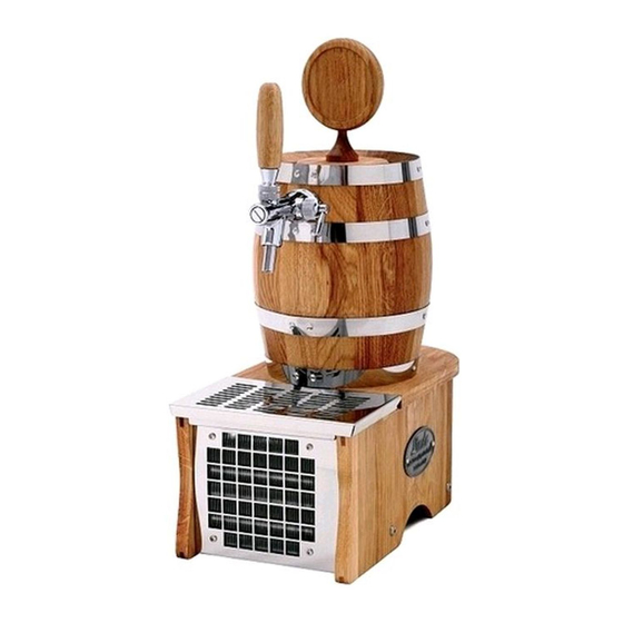
Flow-type luxury cooler
Hide thumbs
1
2
Table Of Contents
3
4
5
6
7
8
9
10
11
12
13
14
15
16
17
18
19
20
page
of
20
Go
/
20
Contents
Table of Contents
Bookmarks
Table of Contents
Table of Contents
Introduction
Description of the Cooler
Machine Plate
General Instructions, Measures and Safety Instructions
Installation and Placement
Electrical Connection
Testing
Warranty
Package Contents
Tap Installation
Keg Coupler Assembly
Beverage Supply Connection and Pressurisation
Beverage Connections
Positioning of the Thermostat
How to Work with Speed Fittings
Temperature and Adjustment
Keg Tapping and Untapping
Putting into Operation
Table of Malfunctions
Spare Parts
Sanitation by Water
Maintenance
Inspection before Every Use
Periodic Checks
Environmental Protection
Advertisement
Quick Links
1
Table of Contents
2
Description of the Cooler
3
Introduction
4
General Instructions, Measures and Safety Instructions
5
Installation and Placement
6
Tap Installation
7
Beverage Supply Connection and Pressurisation
8
Table of Malfunctions
Download this manual
INSTRUCTION MANUAL
LINDR FLOW-TYPE
LUXURY COOLER
ENGLISH
Number 014-2020 REV00
Valid 2020-07-01
Table of
Contents
Previous
Page
Next
Page
1
2
3
4
5
Advertisement
Table of Contents
Need help?
Do you have a question about the GREEN Series and is the answer not in the manual?
Ask a question
Questions and answers
Related Manuals for LINDR GREEN Series
Accessories LINDR SOUDEK 1/8 HP Instructions For Use Manual
Flow type luxury coolers (20 pages)
Kitchen Appliances LINDR PYGMY 30/K profi Instruction Manual
Flow-through contact cooler (20 pages)
Kitchen Appliances LINDR PYGMY 20 Instructions For Use Manual
Flow type contact cooler (17 pages)
Freezer LINDR PYGMY 20/ K Instructions For Use Manual
(9 pages)
Freezer LINDR CWP 300 Green Line 4xpumps new Instruction Manual
(24 pages)
Freezer LINDR 022-2021 Instruction Manual
Flow-through cooler (12 pages)
Freezer LINDR Kontakt 70-K-us Green Line Instruction Manual
(36 pages)
Freezer LINDR KONTAKT 300/K Instruction Manual
(24 pages)
This manual is also suitable for:
Soudek 30/k
Pygmy 25/k
Soudek 20
Soudek 50
Soudek 50/k
Kontakt 55/kprofi
...
Show all
Soudek 50/kprofi
Kontakt 55
Table of Contents
Print
Rename the bookmark
Delete bookmark?
Delete from my manuals?
Login
Sign In
OR
Sign in with Facebook
Sign in with Google
Upload manual
Upload from disk
Upload from URL


Need help?
Do you have a question about the GREEN Series and is the answer not in the manual?
Questions and answers