
Related Manuals for LINDR PYGMY 30/K prof


Summary of Contents for LINDR PYGMY 30/K prof
- Page 1 Gebruikershandleiding The English Manual starts at page 21 LINDR DROOGKOELERS Nederlands Number 012-2020 REV00 Valid 2020-06-01...
- Page 2 De gebruiksaanwijzing bevat belangrijke informatie over het goed en veilig gebruik van deze machine. Deze handleiding is een vertaling van de originele Tsjechische handleiding. LINDR.CZ s.r.o. Sadová 132 503 15 Nechanice, Czech Republic e-mail: info@lindr.cz web: www.lindr.cz,www.lindr.eu...
-
Page 3: Table Of Contents
Inhoudsopgave: Introductie ........Omschrijving van de koeler ........Machine plaat . -
Page 4: Introductie
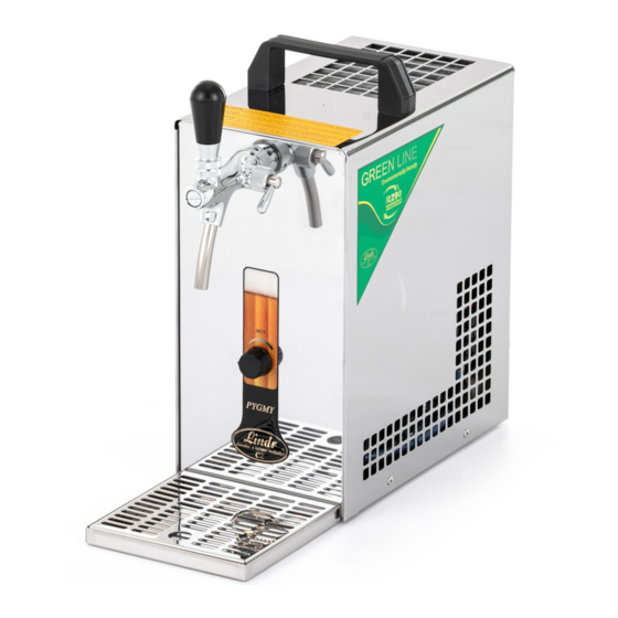
1. INTRODUCTIE: toegestaan en gevaarlijk. De leverancier is Bedankt voor de aankoop van een Lindr product. niet verantwoordelijk voor schade 2. OMSCHRIJVING VAN DE KOELER veroorzaakt door verkeerd gebruik. Dit tapsysteem met ingebouwde compressor GEBRUIK DE MACHINE NIET VOOR EEN... -
Page 5: Aansluiten En Plaatsen
WAARSCHUWING: Plaats nooit gereed- WAARSCHUWING: Plaats na uitpakken de schap of andere objecten in de ventilator. koeler zo dat er voldoende ruimte is om de warmte van de koeler af te voeren. WAARSCHUWING: Raak nooit elektrische onderdelen met natte of vochtige handen aan. WAARSCHUWING: Plaats geen objecten op de koeler die de luchtcirculatie kunnen WAARSCHUWING: Om er voor te zorgen... -
Page 6: Elektrische Aansluiting
6. ELEKTRISCHE AANSLUITING manier te gebruiken die in tegenstrijd is met de handleiding of het ontwerp van het Steek de stekker van de machine in een product zoals gedefinieerd door stopcontact dat voldoet aan de technische fabrikant. Vervangen onderdelen tijdens de specificaties zoals aangegeven op de machine garantie periode zijn ons eigendom. -
Page 7: Tapkraan Monteren
10. TAP KRAAN INSTALLATIE figuur 7 A Draai de compensator kraan (1.) naar beneden. De compensator kraan wordt gebruikt om de uitstromingssnelheid van de drank aan te passen. figuur 7 b Steek de tapkraan recht in de aansluiting. figuur 7 C Draai vast met behulp van de wartel. - Page 8 figuur 8 A figuur 8 b figuur 8 c figuur 8 d Terugslag klepje WAARSCHUWING: Controleer voordat u de de snelsluit koppeling op het 5/8" draad bevestigd of er een siliconen terugslag klepje in de koppeling zit 11.2 Drank aansluiting : Draai een F 5/8“...
-
Page 9: Drank Aansluiten En Druk Instellen
12. DRANK AANSLUITEN EN DRUK INSTELLEN 12.1 Aansluiten en op druk brengen met behulp van ingebouwde compressor (Één-Tap systeem) 1. Drank ingang 5. F 5/8x9.5 mm snelsluit koppeling 2. Lucht uitgang 6. F 5/8x8 mm snelsluit koppeling 3. Lucht compressor schakelaar 7. - Page 10 12.3 Aansluiten en op druk brengen met behulp van de ingebouwde lucht compressor (Twee taps systeem) 1. Drank ingang 5. F 5/8 x 8 mm snelsluit koppeling 2. Lucht uitgang Y 8 x 8 x 8 mm snelsluit koppeling 3. Fust koppeling 7.
- Page 11 12.4 Aansluiten en op druk brengen met een standaard hervulbare CO fles (Twee-Taps systeem) 1. Drank ingang Y 8 x 8 x 8 mm snelsluit koppeling 6. CO drukmeter 2. Fust koppeling 3. F 5/8 x 9.5 mm snelsluit koppeling 7.
-
Page 12: Aansluiten En Afstellen Van De Kontakt 155/R
13. AANSLUITEN EN AFSTELLEN VAN EEN KONTAKT 155/R MET EEN CO FLES 1. Schroef de snelsluit koppelingen op de fust koppeling. 2. Steek de 3/8" (9,5mm) slangen in de snelsluit koppelingen. 3. Verbind de slangen met de juiste snelsluit koppelingen in de koeler. Bij de koppeling staat aangegeven waar deze voor bedoeld is. -
Page 13: Temperatuur Afstellen
14.2 Snelsluit koppeling losmaken figuur 13 c Houd de grijze ring strak tegen de rest van de koppeling en strek de slang los. WAARSCHUWING: Als u de grijze ring niet tegen houdt maar wel aan de slang trekt dan zal de koppeling de slang alleen maar vaster houden. WAARSCHUWING: Slangen moeten niet onder druk staan tijdens het losmaken. -
Page 14: Fust Aan En Afsluiten
16. FUST AAN- EN LOS KOPPELEN WAARSCHUWING: Zorg 16.1 Fust aansluiten ervoor dat de fust koppeling Stappen voor het aansluiten van een bajonet koppeling: schoon is voor het aansluiten! S-type fustkoppeling figuur 14 b figuur 14 A figuur 14 d figuur 14 c figuur 14 e... - Page 15 16.2 Fust loskoppelen Stappen voor het loskoppelen van een bajonetkoppeling: 15 a figuur 15 b figuur 15 c figuur 16.3 Fust aansluiten Stappen voor het aansluiten van een platteschuifkoppeling: WAARSCHUWING: Zorg ervoor dat de fust koppeling A-systeem fustkoppeling schoon is voor het aansluiten! figuur figuur 15 d...
-
Page 16: In Gebruik Nemen
figuur figuur 16 a 16 b 16.4 Fust loskoppelen Stappen voor het loskoppelen van een platteschuifkoppeling: figuur figuur 16 c 16 d 17. IN WERKING STELLEN 1. Sluit de druk en drank slangen aan. 2. Draai de thermostaat naar de 0. 3. -
Page 17: Tabel Met Storingen En Oplossingen
18. TABEL MET STORINGEN EN OPLOSSINGEN Storing Oorzaak Oplossing Er komt geen drank uit Fust verkeerd aangesloten Controleer of de handel van de fustkoppeling goed de koeler omlaag staat. Machine met ingebouwde compressor - zet de compressor aan Schoonmaak water is Zet de koeler uit en wacht tot de drank weer stroomt. -
Page 18: Reserve Onderdelen
Bestellen van onderdelen GEBRUIK ALTIJD ORGINELE ONDERDELEN. De fabrikant of leverancier zijn niet verantwoordelijk voor niet orginele onderdelen of onderdelen die niet aangeraden worden door de fabrikant. 19. RESERVE ONDERDELEN Als u reserve onderdelen besteld vermeld altijd het volgende: • Product type •... -
Page 19: Onderhoud
21. ONDERHOUD werken. De condensor moet elke maand Spoel de tap door met water na elk gebruik stof vuil gecontroleerd worden. (zie schoonmaken met water). Om het stof vuil condensor schoonmaken makkelijker te maken kunt u moet deze schoongemaakt worden, gebruik maken van een spoeladapter (wordt bijvoorbeeld behulp... - Page 20 PRODUCT MODEL KoELVERMOGEN VAN KOELVERMOGEN VAN MAXIMALE KOEL CONTINU THERMISCHE TYPE SPANNING VERMOGEN STROOM AFMETINGEN VAN DE COMPRESSOR DE COMPRESSOR CAPACITEIT (L/UUR) KOEL 6RAIIIENT KOELMIDDEL DE BEHUIZING GEWICHT (HP) ro o·c / TK 45•c PRESTATIE 4T (•c) (B*D*HMM) (KG) PYGMY 20 220-240V R290 1,10...
- Page 21 INSTRUCTION MANUAL LINDR FLOW-THROUGH CONTACT COOLER ENGLISH Number 012-2020 REV00 Valid 2020-06-01...
- Page 22 Read this manual carefully before installing and using the device. It contains important information necessary to ensure that all operations are done prop- erly and safely. This manual is a translation of the original Czech manual. LINDR.CZ s.r.o. Sadová 132 503 15 Nechanice, Czech Republic mobile: + 420 775 715 494 tel.:+420 495 447 239...
- Page 23 Contents: Introduction ........Description of the cooler ........Machine plate .
-
Page 24: Introduction
1. INTRODUCTION: ered impermissible and therefore dangerous. The supplier is not liable for damage caused Thank you for purchasing this LINDR product. by incorrect use. 2. DESCRIPTION OF THE COOLER This beverage dispensing system with built-in DO NOT USE THE DEVICE FOR PURPOSES compressor is ... -
Page 25: Installation And Placement
WARNING: Never place tools or other ob- ject into the fan. WARNING: After unpacking, place the cool- er so that heat created by the cooling unit can WARNING: Never touch electrical compo- be vented sufficiently. nents with wet or damp hands. WARNING: Do not place objects that could WARNING: To ensure the cooling unit prevent air circulation on top of the cooler. -
Page 26: Electrical Connection
6. ELECTRICAL CONNECTION product in a way that is counter to the instruc- tion manual or the product's design as defined Connect the device to a power socket in ac- by the manufacturer. Materials replaced dur- cordance with specifications on the machine ing the validity period of the warranty are our plate of the device. -
Page 27: Tap Installation
10. TAP INSTALLATION figure Turn the compensator lever (1.), so that it points down (see figure). The compensator lever on the tap is used to adjust the flow rate. figure Fit the tap perpendicularly onto the spline. figure Secure with a flare nut and turn left. (loosen to the right). figure Tighten with the enclosed wrench. - Page 28 figure figure figure figure CHECK VALVE WARNING: Before you screw the speed fitting onto the 5/8“ thread, make sure the keg coupler (air inlet for delivery medium) has a lip valve (check valve) fitted on it. 11.2 Outlet for Beverage Screw an F 5/8“...
-
Page 29: Beverage Supply Connection And Pressurisation
12. BEVERAGE SUPPLY CONNECTION AND PRESSURISATION 12.1 Connection and Pressurisation by Built-In Compressor (One-Tap Device) 1. Beverage inlet 5. F 5/8x9.5 mm speed fitting 2. Air outlet 6. F 5/8x8 mm speed fitting 3. Compressor switch Beverage 4. Keg coupler (A-system, S-system, M-system) figure 12.2 Connection and Pressurisation by CO Bottle (One-Tap Device) - Page 30 12.3 Connection and Pressurisation by Built-In Compressor (Two-Tap Device) 1. Beverage inlet 5. F 5/8 x 8 mm speed fitting 2. Air outlet 6. Y 8 x 8 x 8 mm speed fitting 3. Keg coupler (A-system, S-system, M-system) 7. Beverage 4.
- Page 31 12.4 Connection and Pressurisation by Classic CO Bottle (Two-Tap Device) 1. Beverage inlet 5. Y 8 x 8 x 8 mm speed fitting 2. Keg coupler (A-system, S-system, M-system) 6. CO pressure reducing valve 3. F 5/8 x 9.5 mm speed fitting 7.
-
Page 32: Connection And Regulation Of Kontakt 155/R
13. CONNECTION AND REGULATION OF KONTAKT 155/R WITH CO PRESSURE BOTTLE 1. Screw speed fittings onto the keg coupler. 2. Plug 3/8" and 5/16" hoses into the speed fittings on the keg coupler. 3. Connect the 3/8" and 5/16" hose with the speed fittings located on the cooler in accord- ance with the description found on the label above the speed fittings. -
Page 33: Temperature And Adjustment
14.2 Speed Fitting Removal 13 c figure Hold the grey ring tight against the body of the speed fitting and pull out the hose. WARNING: If you do not hold the grey ring but pull at the hose, the speed fitting will cut even deeper into the hose. -
Page 34: Keg Tapping And Untapping
16. KEG TAPPING AND UNTAPPING WARNING: Make sure the 16.1 Keg Tapping adapter is clean before tapping Procedure for tapping a keg using an S-system keg coupler: the keg! S-system keg coupler 14 A 14 b figure figure 14 c 14 d figure figure... - Page 35 16.2 Keg Untapping Procedure for untapping a keg using an S-system keg coupler: 15 a 15 b figure figure 15 c figure 16.3 Keg Tapping Procedure for tapping a keg using an A-system keg coupler: WARNING: Make sure the adapter is clean before tapping A-system keg coupler the keg! 15 d...
-
Page 36: Putting Into Operation
16 a 16 b figure figure 16.4 Keg Untapping Procedure for untapping a keg using an A-system keg coupler: 16 c 16 d figure figure 17. PUTTING INTO OPERATION 1. Interconnect air supply and beverage supply. 2. Set the thermostat to 0 position. 3. -
Page 37: Table Of Malfunctions
18. TABLE OF MALFUNCTIONS Malfunction Cause Removal beverage does not flow keg tapped incorrectly check that the keg coupler lever is pushed down device with built-in compressor - turn on the switch water from sanitation froze turn off the device; then wait until the beverage starts flowing again (may take a few minutes, or hours!) compensator is closed move the compensator lever on the tap... -
Page 38: Spare Parts
Ordering Components ALWAYS USE ORIGINAL COMPONENTS. The manufacturer or supplier bear no responsibility for non-original components or components not recommended by the manufacturer. 19. SPARE PARTS When ordering spare parts, always provide the following: • product type • production year •... -
Page 39: Maintenance
21. MAINTENANCE engineering qualifications. The condenser Flush the beverage tubing of the cooler after must be checked for cleanliness every month. each use with pressurised water (see Sanita- Any dirt found must be cleaned with com- tion by Water). To make flushing easier, use a pressed air or wiped off.
Need help?
Do you have a question about the PYGMY 30/K prof and is the answer not in the manual?
Questions and answers