
Related Manuals for SCHUNK ROTA NCA 160


Summary of Contents for SCHUNK ROTA NCA 160
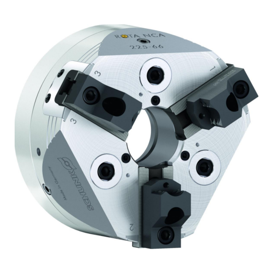
- Page 1 Translation of Original Operating Manual Power Lathe Chuck ROTA NCA Assembly and Operating Manual Superior Clamping and Gripping...
- Page 2 Imprint Imprint Copyright: This manual is protected by copyright. The author is SCHUNK GmbH & Co. KG. All rights reserved. Technical changes: We reserve the right to make alterations for the purpose of technical improvement. Document number: 1155400 Version: 02.00 |26/04/2021|en...
-
Page 3: Table Of Contents
Table of Contents Table of Contents 1 General ........................5 1.1 About this manual ....................5 1.1.1 Presentation of Warning Labels ..............5 1.1.2 Applicable documents ................... 6 1.1.3 Sizes ....................... 6 1.2 Warranty ........................6 1.3 Scope of Delivery ...................... 7 2 Basic safety notes .................... - Page 4 Table of Contents 4 Torques per screw ....................27 5 Assembly ......................... 28 5.1 Installing and connecting ..................28 5.2 Connection thread draw tube ................29 5.3 Checking the chuck mount ..................30 5.4 Assembly ......................... 31 5.4.1 Chuck assembly (with cylindrical recess) ............ 31 5.4.2 Assembly preparation for chuck with reduction or extension flange ..
-
Page 5: General
General General About this manual This manual contains important information for a safe and appropriate use of the product. This manual is an integral part of the product and must be kept accessible for the personnel at all times. Before starting work, the personnel must have read and understood this operating manual. -
Page 6: Applicable Documents
The documents marked with an asterisk (*) can be downloaded on our homepage schunk.com 1.1.3 Sizes This operating manual applies to the following sizes: • ROTA NCA 160-32 • ROTA NCA 200-52 • ROTA NCA 225-66 • ROTA NCA 280-86 • ROTA NCA 330-104... -
Page 7: Scope Of Delivery
General Scope of Delivery Power lathe chuck in the version ordered Mounting screws T-nuts with screws or 3 combination T-nuts Assembly key from size 280 Eye bolt 02.00|ROTA NCA |en... -
Page 8: Basic Safety Notes
Basic safety notes Basic safety notes Intended use This product is intended for clamping workpieces on machine tools and other suitable technical devices. • The product may only be used within the scope of its technical data, ( 3, Page 19). -
Page 9: Constructional Changes
Use of unauthorized spare parts Using unauthorized spare parts can endanger personnel and damage the product or cause it to malfunction. • Use only original spare parts or spares authorized by SCHUNK. Chuck jaws Requirements of the chuck jaws Stored energy can make the product unsafe and poses the danger of serious injuries and considerable material damage. -
Page 10: Environmental And Operating Conditions
• After a collision, the lathe chuck and the chuck jaws must be subjected to a crack test before being used again. Damaged parts must be replaced with original SCHUNK spare parts. • Renew the chuck jaw mounting screws if there are signs of wear or damage. -
Page 11: Personnel Qualification
Basic safety notes If the clamping force has dropped too much or if the base jaws and piston no longer move properly, the chuck must be disassembled, cleaned, and relubricated ( 7, Page 38). Personnel qualification Inadequate qualifications of the personnel If the personnel working with the product is not sufficiently qualified, the result may be serious injuries and significant property damage. -
Page 12: Personal Protective Equipment
Basic safety notes Personal protective equipment Use of personal protective equipment Personal protective equipment serves to protect staff against danger which may interfere with their health or safety at work. • When working on and with the product, observe the occupational health and safety regulations and wear the required personal protective equipment. -
Page 13: Transport
Basic safety notes 2.10 Transport Handling during transport Incorrect handling during transport may impair the product's safety and cause serious injuries and considerable material damage. • When handling heavy weights, use lifting equipment to lift the product and transport it by appropriate means. •... -
Page 14: Protection During Handling And Assembly
Basic safety notes • Disconnect power sources before installation, modification, maintenance, or calibration. Ensure that no residual energy remains in the system. • If the energy supply is connected, do not move any parts by hand. • Do not reach into the open mechanism or movement area of the product during operation. -
Page 15: Protection Against Dangerous Movements
Basic safety notes 2.13.3 Protection against dangerous movements Unexpected movements Residual energy in the system may cause serious injuries while working with the product. • Switch off the energy supply, ensure that no residual energy remains and secure against inadvertent reactivation. •... - Page 16 Basic safety notes DANGER Risk of fatal injury to operating personnel due to the workpiece falling down or being flung out in the event of a power failure In the event of a power failure, the lathe chuck's clamping force may fail immediately and the workpiece may be released in an uncontrolled manner.
- Page 17 Basic safety notes DANGER Possible risk of fatal injury to operating personnel from clothing or hair being caught on the lathe chuck and being dragged into the machine Loose clothing or long hair may become caught on projecting parts of the lathe chuck and be drawn into the machine. •...
- Page 18 Basic safety notes CAUTION Risk of burns due to workpieces with high temperatures. • Wear protective gloves when removing the workpieces. • Automatic loading is preferred. CAUTION Risk of damage due to incorrect choice of clamping position for chuck jaws on workpiece. If an incorrect clamping position is chosen for the chuck jaws on workpiece, the base and top jaws may become damaged.
-
Page 19: Technical Data
Torques per screw Technical data Chuck data ROTA NCA Max. actuating force [kN] * Max. clamping force [kN] Max. speed [rpm] 5500 5000 5000 4000 3500 Stroke per jaw [mm] Piston stroke [mm] Chuck through bore [mm] Weight [kg] 11.5 19.6 62.8 Centrifugal torque of base jaw... -
Page 20: Clamping Force-Rpm Diagrams
The chuck is in perfect condition and lubricated with SCHUNK LINOMAX plus special grease. If one or more of these prerequisites is modified, the graphs will no longer be valid. - Page 21 Torques per screw Clamping force/RPM graph for ROTA NCA 200-52 Clamping force/RPM graph for ROTA NCA 225-66 Clamping force/RPM graph for ROTA NCA 280-89 02.00|ROTA NCA |en...
-
Page 22: Calculations For Clamping Force And Speed
Torques per screw Clamping force/RPM graph for ROTA NCA 330-104 Calculations for clamping force and speed Missing information or specifications can be requested from the manufacturer. Legend Total centrifugal force [N] Centrifugal torque of top jaws [Kgm] Effective clamping force [N] Centrifugal torque of base jaws [Kgm] Minimum required clamping force Speed [rpm]... - Page 23 Torques per screw (–) for gripping from the outside inwards (+) for gripping from the inside outwards DANGER Risk to life and limb of the operating personnel and significant property damage when the RPM limit is exceeded! With gripping from the outside inwards, and with increasing RPM, the effective clamping force is reduced by the magnitude of the increasing centrifugal force (the forces are opposed).
- Page 24 Torques per screw CAUTION This calculated force must not be larger than the maximum clamping force ΣS engraved on the chuck. See also "Chuck data" table ( 3.1, Page 19) From the above formula it is evident that the sum of the effective clamping force F and the total centrifugal force F is multiplied by...
-
Page 25: Calculation Example: Required Initial Clamping Force Fsp0 For A Given Rpm N
Torques per screw 3.3.2 Calculation example: Required initial clamping force Fsp0 for a given rpm n The following data is known for the machining job: • Gripping from the outside in (application-specific) • Machining force F = 3000 N (application-specific) •... -
Page 26: Calculation Of The Permissible Rpm Nzul In Case Of A Given Initial Clamping Force Fsp0
Torques per screw The total centrifugal force can now be calculated: Initial clamping force during shutdown that was sought: 3.3.3 Calculation of the permissible rpm nzul in case of a given initial clamping force Fsp0 The following formula can be used to calculate the permissible RPM for a given initial clamping force during shutdown: CAUTION The calculated permissible RPM may not exceed the maximum... -
Page 27: Grades Of Accuracy
Torques per screw Grades of Accuracy Tolerances for radial and axial run-out accuracy correspond to the Technical Supply Terms for lathe chucks as per DIN ISO 3442-3. Permissible imbalance The ROTA NCA in ungreased state without T-nuts and top jaws corresponds to the balancing quality class 6.3 (according to DIN ISO 1940-1). -
Page 28: Assembly
Assembly Assembly Installing and connecting WARNING Risk of injury due to unexpected movements! If the power supply is switched on or residual energy remains in the system, components can move unexpectedly and cause serious injuries. • Before starting any work on the product: Switch off the power supply and secure against restarting. -
Page 29: Connection Thread Draw Tube
If they cannot be attached directly to the draw tube, an adapter must be used. O-ring ROTA NCA 160-32 M38 x 1.5 2.4 28 38 x 1.5 ROTA NCA 200-53 M67 x 1.5... -
Page 30: Checking The Chuck Mount
Assembly Checking the chuck mount The machine side must be aligned prior to the flange being installed in order to achieve high concentricity of the chuck. To do this, check the contact surfaces on the spindle for concentricity and axial run-out accuracy using a dial indicator. There should be a maximum concentricity error in the centering of the mount of 0.005 mm and a maximum axial run-out error in the contact surfaces of 0.005 mm. -
Page 31: Assembly
Assembly Assembly Lathe chuck assembly 1 Chuck assembly (with cylindrical recess) ( 5.4.1, Page 31) Assembly preparation for chuck with reduction or extension flange ( 5.4.2, Page 34) Assembly preparation for chuck with direct mount ( 5.4.3, Page 34) 5.4.1 Chuck assembly (with cylindrical recess) NOTE... - Page 32 Assembly CAUTION Use a crane to install the chuck. The chuck can be fastened to the eye bolt provided (see Fig. "Lathe chuck assembly" - C ( 5.4, Page 31)). The eye bolt must be removed prior to starting up. The eye bolt is included in the scope of delivery.
- Page 33 Assembly necessary, align at the outer diameter with gentle taps using a hammer. 8 Tighten the fastening screws (item 10) with a torque wrench. The breakaway torques( 4, Page 27) 9 Check the chuck again for concentricity and axial run-out accuracy (see Fig.
-
Page 34: Assembly Preparation For Chuck With Reduction Or Extension Flange
Assembly 5.4.2 Assembly preparation for chuck with reduction or extension flange If the bolt pitch circle of the machine spindle does not correspond to the bolt pitch circle of the lathe chuck, a reduction or extension flange must be used. Affix this flange to the spindle nose prior to chuck assembly. -
Page 35: Function
Function Function Function and handling Wedge-hook chucks are actuated using rotating closed-center or open-center hydraulic cylinders or via a static hydraulic cylinder. The axial tensile and pressure forces are converted to the radial jaw clamping force by the wedge hook angle in the piston and base jaws. -
Page 36: Replacement Or Renewal Of Jaws
Function If the chuck jaws are changed, adjust the stroke control to the new situation. Speed of rotation DANGER Risk of fatal injury to operating personnel if the top speed is exceeded, resulting in workpiece loss and parts flying off! •... - Page 37 Soft standard top jaws must be hardened in the countersink region. They should only be depth-hardened, not surface-hardened. Changing the top jaws When changing the top jaws, the serration has to be cleaned and lightly greased with SCHUNK LINOMAX plus special grease. 02.00|ROTA NCA |en...
-
Page 38: Maintenance
Depending on the operating conditions, the function and clamping force must be checked after a specific period of operation (see "Maintenance intervals" ( 7.2, Page 39)). Only use a calibrated clamping force tester for measuring in the clamping force test (SCHUNK GFT-X). 02.00|ROTA NCA |en... -
Page 39: Maintenance Intervals
If the clamping force has dropped too much or if the base jaws and piston no longer move properly, the chuck has to be disassembled, cleaned, and relubricated. Only use genuine SCHUNK spare parts when replacing damaged parts. Maintenance intervals... - Page 40 12 Remove the screws (item 13). Degrease and clean all parts and check them for damage. Before assembly, grease well with LINOMAX. Only use genuine SCHUNK spare parts when replacing damaged parts. 1 When inserting the base jaw (item 2), make sure that the base jaw is not pushed too far inwards.
-
Page 41: Spare Parts
Seal kit Seal kits Seal kit Ident number ROTA NCA 160 1352529 ROTA NCA 220 1352530 ROTA NCA 225 1352531 ROTA NCA 280... - Page 42 Spare parts Item Designation Quantity a Seal Seal Seal Seal Seal Seal Eye bolt Seal T-nut Screw Screw Emblem Lubrication nipple a = not in size 160 b =only size 280 and 330 c =not in size 33 d= the positions are fixed and cannot be removed e =included in the sealing kit 02.00|ROTA NCA |en...
-
Page 43: Drawing
Drawing Drawing 02.00|ROTA NCA |en... -
Page 44: Declaration Of Incorporation
Declaration of Incorporation in terms of the Directive 2006/42/EG, Annex II, Part 1.B of the European Parliament and of the Council on machinery. Manufacturer/ H.-D. SCHUNK GmbH & Co. Spanntechnik KG Distributor Lothringer Str. 23 D-88512 Mengen We hereby declare that on the date of the declaration the following partly completed machine complied with all basic safety and health regulations found in the directive 2006/42/EC of the European Parliament and of the Council on machinery. -
Page 45: Appendix On Declaration Of Incorporation, As Per 2006/42/Ec, Annex Ii, No. 1 B
Appendix on Declaration of Incorporation, as per 2006/42/EC, Annex II, No. 1 B Appendix on Declaration of Incorporation, as per 2006/42/EC, Annex II, No. 1 B 1. Description of the basic safety and health protection requirements, as per 2006/42/EC, Annex I, that apply to and are fulfilled for the scope of the partly completed machinery: Product designation Wedge hook, power lathe chuck with through-hole... - Page 46 Appendix on Declaration of Incorporation, as per 2006/42/EC, Annex II, No. 1 B Risks due to other hazards 1.5.1 Electricity supply 1.5.2 Static electricity 1.5.3 Energy supply other than electricity 1.5.4 Errors of fitting 1.5.5 Extreme temperatures 1.45.6 Fire 1.5.7 Explosion 1.5.8 Noise...
Need help?
Do you have a question about the ROTA NCA 160 and is the answer not in the manual?
Questions and answers