
Subscribe to Our Youtube Channel
Related Manuals for SCHUNK ROTA NCR 165


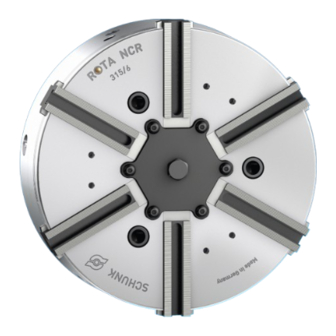
Summary of Contents for SCHUNK ROTA NCR 165
- Page 1 Power chuck ROTA NCR Assembly and Operating Manual Translation of Original Operating Manual...
- Page 2 Imprint Imprint Copyright: This manual is protected by copyright. The author is SCHUNK SE & Co. KG. All rights reserved. Technical changes: We reserve the right to make alterations for the purpose of technical improvement. Document number: 0889064 Version: 05.00 | 19/07/2023 | en...
-
Page 3: Table Of Contents
Table of Contents Table of Contents 1 General ..................... 5 About this manual................1.1.1 Presentation of Warning Labels ............. 1.1.2 Applicable documents ..............1.1.3 Sizes..................1.2 Warranty ................... 1.3 Scope of delivery................. 2 Basic safety notes ................2.1 Intended use..................2.2 Not intended use ................ - Page 4 Table of Contents 5 Mounting ................... 28 5.1 Installing and connecting ..............28 5.2 Checking the chuck mounting ..............28 5.3 Assembly of the chuck on the machine ............ 29 5.3.1 Mounting the chuck with a reduction or extension flange....31 5.3.2 Mounting the chuck by means of a direct mount.......
-
Page 5: General
General 1 General 1.1 About this manual This manual contains important information for a safe and appropriate use of the product. This manual is an integral part of the product and must be kept accessible for the personnel at all times. Before starting work, the personnel must have read and understood this operating manual. -
Page 6: Applicable Documents
Catalog data sheet of the purchased product * Calculation of the jaw centrifugal forces, "Technology" chapter in the lathe chuck catalog * The documents labeled with an asterisk (*) can be downloaded from schunk.com. 1.1.3 Sizes This operating manual applies to the following sizes: ROTA NCR 165;... -
Page 7: Basic Safety Notes
By conversions, changes, and reworking, e.g. additional threads, holes, or safety devices can impair the functioning or safety of the product or damage it. Structural changes should only be made with the written approval of SCHUNK. 05.00 | ROTA NCR | Power chuck | en | 0889064... -
Page 8: Spare Parts
Use of unauthorized spare parts Using unauthorized spare parts can endanger personnel and damage the product or cause it to malfunction. Use only original spare parts or spares authorized by SCHUNK. 2.5 Chuck jaws Requirements of the chuck jaws Stored energy can make the product unsafe and poses the danger of serious injuries and considerable material damage. -
Page 9: Environmental And Operating Conditions
Basic safety notes 2.6 Environmental and operating conditions Required ambient conditions and operating conditions Incorrect ambient and operating conditions can make the product unsafe, leading to the risk of serious injuries, considerable material damage and/or a significant reduction to the product's life span. Make sure that the product is used only in the context of its defined application parameters, [/ 17]. -
Page 10: Personal Protective Equipment
Basic safety notes The following personal qualifications are necessary for the various activities related to the product: Trained electrician Due to their technical training, knowledge and experience, trained electricians are able to work on electrical systems, recognize and avoid possible dangers and know the relevant standards and regulations. -
Page 11: Notes On Safe Operation
Basic safety notes 2.9 Notes on safe operation Incorrect handling of the personnel Incorrect handling and assembly may impair the product's safety and cause serious injuries and considerable material damage. Avoid any manner of working that may interfere with the function and operational safety of the product. -
Page 12: Disposal
Basic safety notes 2.12 Disposal Handling of disposal The incorrect handling of disposal may impair the product's safety and cause serious injuries as well as considerable material and environmental harm. Follow local regulations on dispatching product components for recycling or proper disposal. 2.13 Fundamental dangers General Observe safety distances. -
Page 13: Protection During Commissioning And Operation
Basic safety notes 2.13.2 Protection during commissioning and operation Falling or violently ejected components Falling and violently ejected components can cause serious injuries and even death. Take appropriate protective measures to secure the danger zone. Never step into the danger zone during operation. 2.13.3 Protection against dangerous movements Unexpected movements Residual energy in the system may cause serious injuries while... -
Page 14: Notes On Particular Risks
Basic safety notes 2.13.4 Notes on particular risks DANGER Risk of fatal injury from suspended loads! Falling loads can cause serious injuries and even death. Stand clear of suspended loads and do not step within their swiveling range. Never move loads without supervision. Do not leave suspended loads unattended. - Page 15 Basic safety notes DANGER Possible risk of fatal injury to operating personnel from clothing or hair being caught on the lathe chuck and being dragged into the machine Loose clothing or long hair may become caught on projecting parts of the lathe chuck and be drawn into the machine. The machines and equipment must fulfill the minimum requirements of the EC Machinery Directive;...
- Page 16 Basic safety notes CAUTION Risk of burns due to workpieces with high temperatures. Wear protective gloves when removing the workpieces. Automatic loading is preferred. CAUTION Risk of damage due to incorrect choice of clamping position for chuck jaws on workpiece. If an incorrect clamping position is chosen for the chuck jaws on workpiece, the base and top jaws may become damaged.
-
Page 17: Technical Data
Technical data 3 Technical data 3.1 Chuck data ROTA NCR 1000 Max. actuating force [kN] Max. clamping force [kN] Max. speed [rpm] 4000 3500 3000 2500 1400 1200 1000 Stroke per jaw [mm] Piston stroke 13.5 15.0 18.5 20.0 30.0 30.0 40.0 40.0... -
Page 18: Clamping Force / Speed Diagrams
It is also assumed the chuck is in perfect condition and lubricated with SCHUNK LINOMAX plus special grease . If one or more of these prerequisites is altered, the diagrams will no longer be valid. - Page 19 Technical data Clamping force/RPM graph for ROTA NCR 200 Minimum required clamping force 33% speed of rotation Clamping force/RPM graph for ROTA NCR 250 Minimum required clamping force 33% Speed of rotation Clamping force/RPM graph for ROTA NCR 315 Minimum required clamping force 33% Speed of rotation 05.00 | ROTA NCR | Power chuck | en | 0889064...
- Page 20 Technical data Clamping force/RPM graph for ROTA NCR 400 Minimum required clamping force 33% Speed of rotation Clamping force/RPM graph for ROTA NCR 500 Minimum required clamping force 33% Speed of rotation Clamping force/RPM graph for ROTA NCR 630 Minimum required clamping force 33% Speed of rotation 05.00 | ROTA NCR | Power chuck | en | 0889064...
-
Page 21: Calculations For Clamping Force And Speed
Technical data Clamping force/RPM graph for ROTA NCR 800 Minimum required clamping force 33% Speed of rotation Clamping force/RPM graph for ROTA NCR 1000 Minimum required clamping force 33% Speed of rotation * without centrifugal force compensation ** with centrifugal force compensation 3.3 Calculations for clamping force and speed Missing information or specifications can be requested from the manufacturer. -
Page 22: Calculation Of The Required Clamping Force In Case Of A Given Rpm
Technical data 3.3.1 Calculation of the required clamping force in case of a given The initial clamping force F is the total force impacting radially on the workpiece via the jaws due to actuation of the lathe chuck during shutdown. Under the influence of rotation, the jaw mass generates an additional centrifugal force. - Page 23 Technical data From this we can derive the calculation of the initial clamping force during shutdown: (+) for gripping from the outside inwards (–) for gripping from the inside outwards CAUTION This calculated force must not be larger than the maximum clamping force ΣS engraved on the lathe chuck.
-
Page 24: Calculation Example: Required Initial Clamping Force For A Given Speed
Technical data 3.3.2 Calculation example: required initial clamping force for a given speed Required initial clamping force F for a given RPM n The following data is known for the machining job: Gripping from the outside in (application-specific) Machining force F = 3000 N (application-specific) max. -
Page 25: Calculation Of The Permissible Speed In Case Of A Given Initial Clamping Force
Technical data The total centrifugal force can now be calculated: Initial clamping force during shutdown that was sought: 3.3.3 Calculation of the permissible speed in case of a given initial clamping force Calculation of the permissible RPM n in case of a given initial perm clamping force F The following formula can be used to calculate the permissible... -
Page 26: Grades Of Accuracy
Technical data 3.4 Grades of Accuracy Tolerances for radial and axial run-out accuracy correspond to the Technical Supply Terms for lathe chucks as per DIN ISO 3442-3. 3.5 Permissible imbalance Rotating clamping stations without pallets and workpieces correspond to balancing quality class 6.3 (according to DIN ISO 21940-11). -
Page 27: Torques Per Screw
Torques per screw 4 Torques per screw ightening torques for mounting screws used to clamp the chuck on lathes or other suitable technical equipment (screw quality 10.9) Screw size M10 M12 M14 M16 M18 M20 M22 M24 M27 M30 Admissible torque 290 400 500 1050 1500 (Nm) ightening torques for mounting screws used to attach top jaws... -
Page 28: Mounting
Mounting 5 Mounting 5.1 Installing and connecting WARNING Risk of injury due to unexpected movements! If the power supply is switched on or residual energy remains in the system, components can move unexpectedly and cause serious injuries. Before starting any work on the product: Switch off the power supply and secure against restarting. -
Page 29: Assembly Of The Chuck On The Machine
Mounting Chuck assembly 5.3 Assembly of the chuck on the machine The item numbers specified for the corresponding individual components relate to the chapter Drawings, } 9 [/ 43]. Chucks in sizes 165 and 200 The screws (item 10) cannot be inserted into the piston (item 3) and rotated. - Page 30 Mounting Chuck from size 250 Remove screws (item 39) and take off cover (item 34). Disassemble the three stop pins (item 40). (The pins can be unscrewed on the 2-edge). Completely unscrew screw (item 33) from the piston. Caution: Secure loose pins (item 31) separately. The rotatable screw (item 10) can only be actuated directly using an Allen key.
-
Page 31: Mounting The Chuck With A Reduction Or Extension Flange
Mounting Spindle nose Chuck Cylinder piston in foremost position R1 = Push the chuck piston to its foremost position and measure with a depth gauge. R2 = Draw bar in foremost position. Measure with a depth gauge. 5.3.1 Mounting the chuck with a reduction or extension flange If the chuck is screwed on with an intermediate flange, the following points must be observed: For mounting the chuck on the machine spindle with a short... -
Page 32: Mounting The Chuck By Means Of A Direct Mount
Mounting The chuck is mounted after the flange has been aligned. During this, it must be ensured that any contaminations on the flange and on the chuck contact surfaces are removed. WARNING Risk of injury from falling of the unit during transport and assembly! The use of a crane is necessary for assembling the lathe chuck. -
Page 33: Replacing Or Adding To Jaws
Mounting After mounting the flange on the chuck, the chuck must be mounted on the machine spindle. Push the chuck onto the intermediate flange. During this, it must be ensured that the through-holes for attaching the chuck coincide with the threaded holes of the flange (see Fig. "Assembly of the chuck"... -
Page 34: Switching The Compensating Clamping On And Off
Mounting Tighten the mounting screws of the top jaws with a torque wrench. Never tighten the Allen key with an extension pipe or by hitting it with a hammer. WARNING If the workpiece is clamped at the end of the base jaw stroke, this poses the risk that the entire clamping force is not transferred onto the workpiece. -
Page 35: Option With Bearing Plate
Mounting 5.6 Option with bearing plate Using the conversion kit, a workpiece rest can be produced on the chuck face. In addition, an air control can be created. The bearing plate (Item 44) has not been pre-drilled for the workpiece bolts (Item 45). Instead, the radial position of the workpiece bolts (Item 45) must be produced by the customer in accordance with the specific workpieces to be machined. -
Page 36: Function
Function 6 Function 6.1 Function and handling The lever chuck is actuated using a rotating solid or through-hole cylinder. The axial tension and pressure forces are diverted into the radial clamping force via lever action. The clamping and opening path of the chuck jaws is determined by the clamping cylinder. - Page 37 Function Speed of rotation DANGER Risk of fatal injury to operating personnel if the top speed is exceeded, resulting in workpiece loss and parts flying off! A reliable speed limiter must be installed in the machine tool or technical equipment and proof must be provided that the speed limiter is effective! 05.00 | ROTA NCR | Power chuck | en | 0889064...
-
Page 38: Maintenance
(see chapter "Maintenance intervals" [/ 38]). Measure the clamping } 7.2 force only by using a calibrated Grip Force Tester (SCHUNK SGT 270). Technical Condition The base jaws must move evenly at the smallest possible operating pressure (cylinder). -
Page 39: Disassembly And Assembly Of The Chuck
Maintenance 7.3 Disassembly and assembly of the Chuck The item numbers specified for the corresponding individual components relate to the chapter Drawings, } 9 [/ 43]. The lathe chuck must only be disassembled once it has been uninstalled (see chapter "Mounting the chuck to the machine" [/ 28]). -
Page 40: Disassembling And Assembling The Piston
Maintenance Degrease and clean all parts and check them for damage or wear. Only use genuine SCHUNK spare parts when replacing damaged parts. Before assembly, grease well with LINOMAX special grease paste. The lathe chuck is assembled in the same way but in the reverse order. -
Page 41: Spare Parts
Spare parts 8 Spare parts When ordering spare parts, it is imperative to specify the type, size and above all the manufacturing no of the chuck. Seals, sealing elements, screw connections, springs, bearings, screws and wiper bars plus parts coming into contact with the workpiece are not covered by the warranty. - Page 42 Spare parts Item Designation Quantity Pan-head screw Countersunk screw connecting member Set-screw piston The plunger pin Torque pin seat of bearing (165/200/250) Eye bolt Screw seal Adapter seal Piston seal Mounting seal Chuck body seal Pipe seal Locking screw seal Workpiece bolt seal (workshop star option) Screw seal Conical lubrication nipple...
-
Page 43: Assembly Drawings
Assembly drawings 9 Assembly drawings 05.00 | ROTA NCR | Power chuck | en | 0889064... - Page 44 Assembly drawings 05.00 | ROTA NCR | Power chuck | en | 0889064...
- Page 45 05.00 | ROTA NCR | Power chuck | en | 0889064...
- Page 46 05.00 | ROTA NCR | Power chuck | en | 0889064...
- Page 47 H.-D. SCHUNK GmbH & Co. Spanntechnik KG Lothringer Str. 23 D-88512 Mengen Tel. +49-7572-7614-0 Fax +49-7572-7614-1099 info@de.schunk.com schunk.com Folgen Sie uns I Follow us Wir drucken nachhaltig I We print sustainable...
- Page 48 2B, NCA, NCD, NCE, NC, NCF, NCK, NCO, NCR, NCS, NCX, TH, THW Heinz-Dieter SCHUNK GmbH & Co. Spanntechnik KG certifies that the above-mentioned products, when used as intended and in compliance with the operating manual and the warnings on the product, are safe according to the national regulations and: −...
Need help?
Do you have a question about the ROTA NCR 165 and is the answer not in the manual?
Questions and answers