
Related Manuals for SCHUNK VERO-S NSE-A3 Series


Summary of Contents for SCHUNK VERO-S NSE-A3 Series
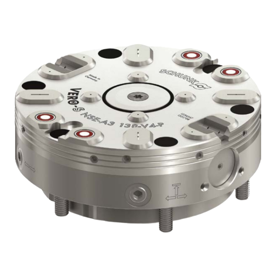
- Page 1 Translation of Original Operating Manual VERO-S quick-change pallet system NSE-A3 Assembly and Operating Manual Superior Clamping and Gripping...
- Page 2 Imprint Copyright: This manual is protected by copyright. The author is SCHUNK GmbH & Co. KG. All rights reserved. Any reproduction, processing, distribution (making available to third parties), translation or other usage - even excerpts - of the manual is especially prohibited and requires our written approval.
-
Page 3: Table Of Contents
Table of contents Table of contents 1 General ........................5 1.1 About this manual ....................5 1.1.1 Presentation of Warning Labels ..............5 1.1.2 Applicable documents ................... 6 1.1.3 Design ......................6 1.2 Warranty ........................6 1.3 Scope of delivery ...................... 7 1.4 Accessories ....................... - Page 4 Table of contents 4.5 Clamping slide monitoring ..................30 4.6 Pneumatic circuit diagram..................33 4.7 Screw tightening torques ..................36 4.8 AFS 138 electronic monitoring systems (optional) ..........36 5 Function ........................37 5.1 KVS3 138 cone seal ....................37 5.2 Media transfer unit....................
-
Page 5: General
General General About this manual This manual contains important information for a safe and appropriate use of the product. This manual is an integral part of the product and must be kept accessible for the personnel at all times. Before starting work, the personnel must have read and understood this operating manual. -
Page 6: Applicable Documents
• Catalogue data sheet of the rotary indexing table * • Technical data sheet for optional attachments * The documents marked with an asterisk (*) can be downloaded on our homepage schunk.com 1.1.3 Design This guide applies to the following versions Quick-Change Pallet System •... -
Page 7: Scope Of Delivery
General Scope of delivery The scope of delivery includes 1 quick-change pallet system in the variant ordered • 1 module accessory kit consisting of: 4 O-rings Ø 9 x 1.5 6 cover caps 6 fastening screws M8 1 fitting screw M8 •... -
Page 8: Basic Safety Notes
Implementation of structural changes By conversions, changes, and reworking, e.g. additional threads, holes, or safety devices can impair the functioning or safety of the product or damage it. • Structural changes should only be made with the written approval of SCHUNK. 02.00|1376941_NSE-A3 |en... -
Page 9: Spare Parts
Use of unauthorized spare parts Using unauthorized spare parts can endanger personnel and damage the product or cause it to malfunction. • Use only original spare parts or spares authorized by SCHUNK. Environmental and operating conditions Required ambient conditions and operating conditions... -
Page 10: Personnel Qualification
Basic safety notes Personnel qualification Inadequate qualifications of the personnel If the personnel working with the product is not sufficiently qualified, the result may be serious injuries and significant property damage. • All work may only be performed by qualified personnel. •... -
Page 11: Personal Protective Equipment
Basic safety notes Personal protective equipment Use of personal protective equipment Personal protective equipment serves to protect staff against danger which may interfere with their health or safety at work. • When working on and with the product, observe the occupational health and safety regulations and wear the required personal protective equipment. -
Page 12: Transport
Basic safety notes Transport Handling during transport Incorrect handling during transport can make the product unsafe and risk serious injuries and considerable material damage. • During transport and handling, secure the product to prevent it from falling. • Do not walk under suspended loads. 2.10 Malfunctions Behavior in case of malfunctions... -
Page 13: Fundamental Dangers
Basic safety notes 2.12 Fundamental dangers General • Observe safety distances. • Never deactivate safety devices. • Before commissioning the product, take appropriate protective measures to secure the danger zone. • Disconnect power sources before installation, modification, maintenance, or calibration. Ensure that no residual energy remains in the system. -
Page 14: Protection During Commissioning And Operation
Basic safety notes 2.12.2 Protection during commissioning and operation Falling or violently ejected components Falling and violently ejected components can cause serious injuries and even death. • Take appropriate protective measures to secure the danger zone. • Never step into the danger zone during operation. Manual loading Falling clamping pallets •... -
Page 15: Notes On Particular Risks
Basic safety notes 2.12.4 Notes on particular risks DANGER Risk of fatal injury from suspended loads! Falling loads can cause serious injuries and even death. • Stand clear of suspended loads and do not step within their swiveling range. • Never move loads without supervision. •... - Page 16 Basic safety notes WARNING Risk of injury when the clamping pin axis is being used in a horizontal position or during overhead applications due to the device or pallet falling down. • Use a crane or a transport truck when transporting workpieces or clamping pallets.
- Page 17 Basic safety notes CAUTION Risk of injury from pressurized media transfer interfaces. The actuated clamping device on top of these may moved spontaneously as a result. • Use safety valves or safety switches. • Do not actuate media transfer units until loading is completed. •...
-
Page 18: Product Description
Product description Product description Description of design and version Clamping module Equipment type Torque Cone Media pin V4 seal transfer unit NSE-A3 138 NSE-A3 138-V4 NSE-A3 138-V4-P Hydrokomp NSE-A3 138-V4-P1 Technical data Designation ID No. Holding force* Pull down Pull down Type (M10 / M12 / M16) force... -
Page 19: Technical Data For Coupling Elements Of Media Transfer Unit
Product description Actuating pressure 6 bar Repeat accuracy [mm] < 0.005 mm Pull-in stroke max. 0.9 mm Loading weight for versions with cone seal 3.2 kg Loading weight for cone seal when using a weaker compression spring (optionally 2 kg available) Installation position Operating temperature... -
Page 20: Assembly
Assembly Assembly Pre-assembly Request our installation drawings if installing the module in the customer's clamping stations yourself. The installation position must be observed when performing the installation yourself. Partial installation Do not use Full installation NOTICE With installation location 2, the clamping slide can be blocked by chips and dirt. - Page 21 Assembly WARNING Risk of injury due to unexpected movements when installing and removing the cone seal! This can cause components to move unexpectedly when working on the cone seal, resulting in injuries. • Before starting all work on the product, refer to the cone seal chapter.
-
Page 22: Fastening And Connection
Assembly Fastening and connection Flatness If several linked clamping modules are mounted, make sure that the flatness and height deviation of the outer ring locating surfaces from clamping module to clamping module (with respect to a 200 mm gauge) is ≤ 0.03 mm. The gauge deviation may not exceed ±... - Page 23 Assembly Air bleed screw for applications without turbo Connection for blow-out / air purge The air connection for the blow-out air / air purge is achieved via the bottom M7 connection thread by installation of a screw-in union. Alternatively, the air supply can be actuated from a channel bore hole leading out of the installation location of the clamping module.
- Page 24 The NW3 coupling nipples to be used for the side of the clamping pallet as well as the relevant installation drawing can be requested from SCHUNK. NOTE If the media transfer function is used, ensure that the coupling elements are depressurized and ventilated when loading and unloading the clamping pallet.
-
Page 25: Mounting
Assembly Number of modules At least nominal hose width 4 mm 2, 3, 4 6 mm from 5 8 mm When disconnecting hose lines, the relevant openings of the air supply connections must be protected with seal plugs or sealing caps to prevent the ingress of dirt or coolant. - Page 26 Assembly 02.00|1376941_NSE-A3 |en...
-
Page 27: Clamping Pins Spa 40, Spb 40, Spc 40, Spg 40
Only bolts of strength class 12.9 may therefore be used for this. Only original SCHUNK clamping pins may be used. If the clamping pins are to be used in customer-owned devices,... - Page 28 If clamping pins are used outside of SCHUNK pallets, for example in customer-specific devices or workpieces, the outer diameter of the part to be clamped must be large enough to completely cover the inner support area of the quick-change pallet system.
- Page 29 Assembly Usage/arrangement of the different types of clamping pins 02.00|1376941_NSE-A3 |en...
-
Page 30: Information To Clamping Pin Spg 40
2 bar. Monitoring requires a pressure gauge, an adjustable throttle and an air gap sensor. For monitoring of the clamping slide, the designated connection must be actuated a floor-side bore hole. The installation drawings can be requested from SCHUNK in case of self-installation. 02.00|1376941_NSE-A3 |en... - Page 31 Assembly Dynamic pressure NSE-A3 138 No. Description Hose-free direct connection for unlocking <-- --> Hose-free direct connection for turbo --> <-- Hose-free direct connection for dynamic pressure monitoring of the "CLAMPED" clamping slide position Hose-free direct connection for dynamic pressure monitoring of the "OPEN" clamping slide position Air outlet for dynamic pressure monitoring of the clamping slide position "CLAMPED"...
- Page 32 Assembly NOTICE If the pneumatic monitoring function for monitoring the clamping slide position is not used, it must be ensured that the quick-change pallet systems can be loaded or unloaded without being damaged. • Before loading or unloading the clamping pallet ensure that all integrated clamping modules are unlocked.
-
Page 33: Pneumatic Circuit Diagram
Assembly Pneumatic circuit diagram Pneumatic circuit diagram with media transfer unit for pneumatics, hydraulics, vacuum Unlocking connection; actuation with max. 6 bar Turbo connection; actuation with max. 6 bar Slide monitoring for module "OPEN"; actuation with max. 2 bar Slide monitoring for module "CLAMPED"; actuation with max. 2 bar Media transfer unit for pneumatic, hydraulic or vacuum, can be coupled when depressurized;... - Page 34 Assembly Observe the following when controlling: Turbo function: • The actuating pressure for the turbo function must not exceed 6 bar. Clamping slide monitoring • The max. pressure for clamping slide monitoring is 2 bar. • Limit volumetric flow to 15 l/min. •...
- Page 35 Assembly Dynamic pressure NSE-A3 138 No. Designation Hose-free direct connection for unlocking <-- --> Hose-free direct connection for turbo --> <-- Hose-free direct connection for dynamic pressure monitoring of the "CLAMPED" clamping slide position Hose-free direct connection for dynamic pressure monitoring of the "OPEN" clamping slide position Air outlet for dynamic pressure monitoring of the clamping slide position "CLAMPED"...
-
Page 36: Screw Tightening Torques
Assembly Screw tightening torques Tightening torques for mounting clamping pins (Screw quality 12.9) Screw size Tightening torque (Nm) Tightening torques for mounting clamping modules (Screw quality 10.9) Screw size Tightening torque (Nm) Tightening torque for the countersunk screw on the cone seal (Screw quality A2-70) Screw size Tightening torque (Nm) -
Page 37: Function
Function Function The item numbers specified for the corresponding individual components relate to chapter drawings.( 10, Page 46) KVS3 138 cone seal The quick-change pallet system is equipped with a cone seal to protect the change interface. The sealing unit can be spring-loaded and reset when the module is unlocked. -
Page 38: Media Transfer Unit
The NW3 coupling nipples to be used (I.D. no. 1374387) for the side of the clamping pallet as well as the relevant installation drawing can be requested from SCHUNK. NSE-A3 138-V4-P1 has four open media transfer unit interfaces. -
Page 39: Operation
In this case, the system must be inspected and damaged parts must be replaced immediately. Only original SCHUNK spare parts may be used! WARNING Risk of injury due to destruction of pallets or workpieces in the case of incorrect actuation caused by incorrect operation. - Page 40 Operation WARNING Risk of injury due to losing pallets or workpieces if the supply of compressed air drops or fails, and due to the clamping pins immediately closing • Do not reach into the clamping module. • Use pressure maintenance valves. •...
-
Page 41: Maintenance And Care
If the clamping module has to be disassembled, send the module to SCHUNK for repair. The back cover of the clamping module is spring preloaded and must only be removed by trained specialist personnel. The cover... -
Page 42: Troubleshooting
Defective air connections Check air supply Pressure below minimum Check operating pressure (min. 5 bar) A component is broken (e.g. due to Replace the module or send it to SCHUNK for overloading) repair Excess tensile load on clamping pins Reduce support weight... -
Page 43: Malfunctions When Loading And Unloading The Change Interface With Fitted Cone Seal
Troubleshooting Malfunctions when loading and unloading the change interface with fitted cone seal Possible cause Remedial measures Cone seal jams when actuated Remove cone seal from the module and clean The pressed down cone seal does not Remove cone seal and clean it. Check return to its original position components for damage. -
Page 44: Wear Parts Set And Parts Lists
The bearing shells may only be replaced in case of damage as part of maintenance work by SCHUNK. To do so, the quick-change pallet module must be sent to SCHUNK for maintenance. Parts lists... - Page 45 Wear parts set and parts lists Item Designation NSE-A3 138 NSE-A3 138- NSE-A3 138- NSE-A3 138- V4-P V4-P1 1364306 1364307 1351708 1339726 Slide bearing collar bushing 4 Cylindrical pin Cylindrical screw Compression spring Set-screw Set-screw Set-screw G1/8" locking screw Cylindrical screw Flex insert Coupling mechanism Stop sleeve...
-
Page 46: Assembly Drawings
Assembly Drawings Assembly Drawings 10.1 Assembly 02.00|1376941_NSE-A3 |en... -
Page 47: Cone Seal Kvs3 138
Assembly Drawings 10.2 Cone seal KVS3 138 02.00|1376941_NSE-A3 |en... -
Page 48: Translation Of Original Declaration Of Incorporation
Translation of original declaration of incorporation in terms of the Directive 2006/42/EG, Annex II, Part 1.B of the European Parliament and of the Council on machinery. Manufacturer/ H.-D. SCHUNK GmbH & Co. Spanntechnik KG Distributor Lothringer Str. 23 D-88512 Mengen... -
Page 49: Appendix On Declaration Of Incorporation, As Per 2006/42/Ec, Annex Ii, No. 1 B
Appendix on Declaration of Incorporation, as per 2006/42/EC, annex II, No. 1 B Appendix on Declaration of Incorporation, as per 2006/42/EC, annex II, No. 1 B 1. Description of the basic safety and health protection requirements, as per 2006/42/EC, Annex I, that apply to and are fulfilled for the scope of the partly completed machinery: Product VERO-S quick-change pallet system designation:... - Page 50 Appendix on Declaration of Incorporation, as per 2006/42/EC, annex II, No. 1 B Required characteristics of guards and protective devices 1.4.1 General requirements 1.4.2 Special requirements for guards 1.4.2.1 Fixed guards 1.4.2.2 Interlocking movable guards 1.4.2.3 Adjustable guards restricting access 1.4.3 Special requirements for protective devices Risks due to other hazards...
Need help?
Do you have a question about the VERO-S NSE-A3 Series and is the answer not in the manual?
Questions and answers