Degelman PRO-TILL 20 Operator's & Parts Manual
Hide thumbs
Also See for PRO-TILL 20:
- Operator's & parts manual (49 pages) ,
- Quick start manual (2 pages) ,
- Quick start manual (2 pages)
Table of Contents
Advertisement
Quick Links
D E G E L M A N
I N D U S T R I E S
B O X
8 3 0 - 2 7 2
I N D U S T R I A L
R E G I N A ,
S K ,
C A N A D A ,
F A X 3 0 6 . 5 4 3 . 2 1 4 0
P H 3 0 6 . 5 4 3 . 4 4 4 7
1 . 8 0 0 . 6 6 7 . 3 5 4 5
D E G E L M A N . C O M
L P
D R I V E ,
S 4 P
3 B 1
OPERATOR & PARTS
MANUAL
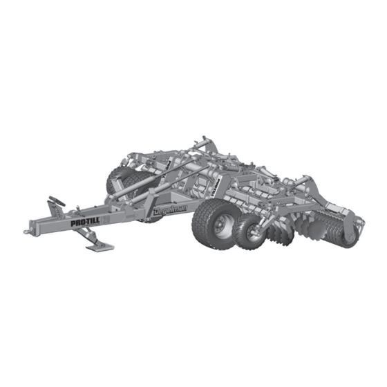
PRO-TILL
20/20HD 26/26HD
Serial Numbers: PTL4652 and above
143433 v1.0
Advertisement
Table of Contents

Subscribe to Our Youtube Channel
Related Manuals for Degelman PRO-TILL 20


Summary of Contents for Degelman PRO-TILL 20
- Page 1 OPERATOR & PARTS MANUAL 143433 v1.0 PRO-TILL D E G E L M A N I N D U S T R I E S B O X 8 3 0 - 2 7 2 I N D U S T R I A L D R I V E , 20/20HD 26/26HD R E G I N A ,...
- Page 3 QUICK-START GUIDE WARRANTY PRO-TILL 20/26 REMEMBER! You must complete Product * Refer to operators manual for complete safety and operation info. Registration to be eligible for Warranty. Connect Hydraulics CONSTANT FLOAT PRESSURE DEPTH WINGS TRANSPORT JACK REAR DISC DEPTH IMPORTANT: Constant Wing Pressure The Wing Cylinder Circuit includes a Down Pressure Valve.
- Page 4 Put in Field Position 1” IMPORTANT: Operator must read and understand the tractor manual in order to place the required hydraulic circuits into oat position or constant pressure position. Float iii) Transport Cylinders Constant Pressure Wing Cylinders Fine Pitch Fine Pitch Rear Disc Front Disc Adjustment...
-
Page 5: Table Of Contents
* Reference Sheet Quick-Start Guide OPERATORS SECTION - TABLE OF CONTENTS IMPORTANT Safety Notice Introduction Safety Hook-Up Transport Transport to Field Position Field to Transport Position Operation Pre-Operation Checklist Operation Guidelines / Suggestions Setting Disc Depth Scraper Settings Troubleshooting Service & Maintenance Maintenance Checklist Maintenance Free Pins &... - Page 6 IMPORTANT SAFETY REMINDER DANGER NEVER PARK, UNHOOK, or RAISED SERVICE Pro-Till with REAR WINGS DANGER If the front hitch becomes disconnected in this position the front hitch will raise suddenly and the back of the machine will drop! CHANGING DISCS AND SERVICING The best position to safely change or service the discs on the Pro-Till is when it is secured in the winged...
-
Page 7: Introduction
Degelman PRO-TILL is the fastest and most versatile piece of tillage equipment you will ever own. Use this manual as your first source of information about this machine. -
Page 8: Safety
CAUTION: Indicates a potentially hazardous situation CAUTION that, if not avoided, MAY result in minor or moderate injury if proper practices are not taken, or, serves as a reminder to follow appropriate safety practices. 143433 - PRO-TILL 20|26 (15-January-2021) - Page 9 GENERAL SAFETY YOU are responsible for the safe operation and 1. Read and understand the Operator’s maintenance of your Degelman PRO-TILL. Manual and all safety signs before YOU must ensure that you and anyone else who operating, maintaining or adjusting.
-
Page 10: Hook-Up
8. Install a safety chain between the tractor and the hitch. 9. Connect lights (electrical socket plug) to tractor. 10. Raise the hydraulic hitch jack. 11. When unhooking from the tractor, reverse the above procedure. 143433 - PRO-TILL 20|26 (15-January-2021) -
Page 11: Transport
6. Check that the transport tires are properly inflated to 58 PSI (400 kPa). IMPORTANT Under NO RIDERS CIRCUMSTANCES should there ever be riders while the Pro-Till is in transport. 143433 - PRO-TILL 20|26 (15-January-2021) -
Page 12: Transport To Field Position
This will ensure constant down pressure is applied to the wings and the machine can still contour over uneven terrain effectively. Adjust wing circuit flow down to 20-30% to reduce heat build-up. (Refer to your tractor's manual for proper procedures.) 143433 - PRO-TILL 20|26 (15-January-2021) -
Page 13: Field To Transport Position
E. When the wing frame rollers using the Wing Cylinders (2). are in proper position above the transport holders, lightly lower the wings in place by retracting the Transport cylinders (#3) to gently set the wings onto the holders. 143433 - PRO-TILL 20|26 (15-January-2021) -
Page 14: Operation
1. Check all hardware. Tighten as required. outlined in the adjustments section. If excessive disc wear is evident, replacement may be 2. Check all hydraulic system connections. required. Refer to maintenance section. Tighten if any are leaking. 143433 - PRO-TILL 20|26 (15-January-2021) -
Page 15: Operation Guidelines / Suggestions
- 22" Disc configuration uses 20" Outer Disc - RH Rear the “Setting Disc Depth” section. - 26" Disc configuration uses 22" Outer Disc - RH Rear 143433 - PRO-TILL 20|26 (15-January-2021) -
Page 16: Setting Disc Depth
2 - Stop the machine. 3 - Adjust the height/angle so the deflector is running Start with the deflector higher than necessary until desired just slightly above the ground. cutting depth is achieved, then adjust deflector. -10- 143433 - PRO-TILL 20|26 (15-January-2021) - Page 17 - Loosen the two deflector adjustment bolts - Fully raise the deflector plate to the top of the adjustment slot. - Then retighten the bolts. Optional: The Dirt Deflector Assembly may be removed & stored. -11- 143433 - PRO-TILL 20|26 (15-January-2021)
- Page 18 To correct for this and achieve straight tracking, either the rear discs may need to be raised or the front discs lowered by adjusting the number of the depth stops. -12- 143433 - PRO-TILL 20|26 (22-February-2021)
-
Page 19: Scraper Settings
Double Sided Scraper Blades Note: When blades are being reversed, the complete section must be changed at the same time or adjustment will not work properly. -13- 143433 - PRO-TILL 20|26 (15-January-2021) -
Page 20: Troubleshooting
Troubleshooting - Pro-Till 20/26 Plugging disc rows in wet conditions: Rear discs or roller not engaging in very hard soil: - Ensure roller is turning & scrapers are set properly. - Adjust pitch so front discs are higher by removing a - Raise machine working depth. - Page 21 Troubleshooting - Pro-Till 20/26 Leaving a groove between passes: End of wing discs cutting deeper or shallower than center: - Adjust deflector down to fill groove. - Fully extend depth control cylinders & hold for 30 - Adjust deflector assembly in to fill groove.
-
Page 22: Service & Maintenance
Only disconnect when unit is on level ground in the proper Annually transport or field position. • Bolt tightness • Wheel bearings IMPORTANT: Safely secure Pro-Till in winged forward transport position when changing or servicing discs. -16- 143433 - PRO-TILL 20|26 (15-January-2021) - Page 23 5. Ensure hoses are properly clamped and secured in 915 (1240) 1310 (1780) position after routing is complete to provide a cleaner 1250 (1695) 1785 (2420) installation and prevent possible damage or hazards. 1600 (2175) 2290 (3110) v1.1 -17- 143433 - PRO-TILL 20|26 (14-May-2021)
- Page 24 2. Align, thread into place and hand tighten. 8. Inspect to ensure that O-ring is not pinched and that washer is seated fl at on the face of the port. 3. Tighten to proper torque from the table shown above. -18- 143433 - PRO-TILL 20|26 (14-May-2021)
- Page 25 8. Use hydraulic cylinder jack. 10. Pump grease into hub through grease fitting until 9. Oil any exposed chrome shafts on the hydraulic lubricant can be seen from dust seal. cylinders to prevent rusting. -19- 143433 - PRO-TILL 20|26 (15-January-2021)
- Page 26 5. Apply Loctite anti-seize before installing cylinder end cap. 6. Torque cylinder end cap to 440 lb.ft (600 N.m). 7. Tighten Set Screw on end cap to 6 lb.ft (8 N.m). -20- 143433 - PRO-TILL 20|26 (15-January-2021)
- Page 27 8. When both bushings are installed to the Install proper depth, install the new seals. Seal 9. Re-assemble all other 5/16" necessary components. IMPORTANT: DO NOT use oil or grease on pins or bushing surfaces when re-installing. -21- 143433 - PRO-TILL 20|26 (15-January-2021)
- Page 28 Service & Maintenance DECAL LOCATION OVERVIEW 142969 - Decal, Warning 142982 - Decal, Pro-Till 20 - 4” (2) - Float Cylinders-sm (2) 142984 - Decal, Pro-Till 26 - 4” (2) 142986 - Decal, Warning 142788 - Decal, Warning 142988 -...
-
Page 29: Pro-Till Section Overview
Hitch Frame Wheel Rockshaft Hyd Jack Assembly Center Frame RH Wing Disc Gangs Wing Roller Frame LH Wing Scraper LH Wing Endwheel Frame Cage LH Wing - or - Rubber Roller Disc Gangs Roller -23- 143433 - PRO-TILL 20|26 (15-January-2021) -
Page 30: Hitch Pole Frame Components
575194 - Pin Head (4) 573175 - Jack Leg 131020 - Flat Assembly (1) washer, 1 F436 (16) 118911 - Lock Nut, 1 (8) 118134 - Bolt, 1 x 3 GR8 (8) 573180 - Jack Base Assembly (1) -24- 143433 - PRO-TILL 20|26 (15-January-2021) - Page 31 117565 - Bolt, 1 x 4-1/2 UNC GR8 (1) 131020 - Flat washer, 1 F436 (1) 118911 - Lock Nut, 1 (1) 118615 - Flat washer, 1 x 3-1/8 (1) 116302 - Safety Chain Assembly (1) -25- 143433 - PRO-TILL 20|26 (15-January-2021)
-
Page 32: Wheel & Rockshaft Components
4 Hole - #SE49 (1) 118723 - Stud, Wheel 131838 - Dust Cap - #DC27 (1) (Replacement Part) 118641 - Bolt, 5/16 x 1/2 (4) 10 BOLT PATTERN 118712 - Nut, Wide Base 3/4 UNF GR8 (10) -26- 143433 - PRO-TILL 20|26 (15-January-2021) -
Page 33: Center Frame Components
575194 - Pin Head (2) Routing page for Mounts with: components) 118767 - Bolt, 7/8 x 3 GR8 (2) 118774 - Flat washer, 7/8 - F436 (4) 117416 - Lock Nut, 7/8 Unitorq (2) -27- 143433 - PRO-TILL 20|26 (15-January-2021) -
Page 34: Wing Frame Components
131745 - Bearing Cone, LM501349 (1) 131741 - Flat Washer, 1-5/16 x 1/4 (1) Also Requires: 131776 - Wheel Nut, 5/8 -18 UNF (8) 131740 - Castle Nut, 1-1/4 (1) Torque, 5/8 Wheel Nut: 185-190 lb.ft (250-260 N.m) -28- 143433 - PRO-TILL 20|26 (15-January-2021) - Page 35 780278 - Hose Clamp, Set (6) 118774 - Flat washer, 7/8 - F436 (2) 118774 - Flat washer, 7/8 - F436 (4) 117416 - Lock Nut, 7/8 Unitorq (1) 117416 - Lock Nut, 7/8 - Unitorq (2) -29- 143433 - PRO-TILL 20|26 (15-January-2021)
- Page 36 573841 - Deflector Plate (1) 573832 - Mounts with: Deflector 117414 - Lock Nut, 3/4 Unitorque (2) Mount Arm (1) 118635 - Flat Washer, 3/4 x 2-1/4 (2) 117438 - Bolt, CRG 3/4 x 2-1/2 GR8 (2) -30- 143433 - PRO-TILL 20|26 (15-January-2021)
-
Page 37: Disc Arm Components & Disc Options
(11 Discs + Outer) 573773 - Gang Section Assembly (1) c/w 573774 - Gang Mounting Frame (1) Back Row (LH) (11 Discs) 573771 - Gang Section Assembly (1) c/w 573775 - Gang Mounting Frame (1) -31- 143433 - PRO-TILL 20|26 (15-January-2021) - Page 38 573753 - Gang Section Assembly (1) c/w 573754 - Gang Mounting Frame (1) Front Row (LH) (16 Discs) Back Row (LH) (15 Discs) 573751 - Gang Section Assembly (1) c/w 573755 - Gang Mounting Frame (1) -32- 143433 - PRO-TILL 20|26 (15-January-2021)
- Page 39 400 lb . ft (542 N . m) Disc Hub Components 131415 - Disc Hub Unit (Varied Suppliers) Replacement O-Rings listed below: INA - Markings SKF - Markings 121080 - O-Ring, 121082 - O-Ring, Nitrile M6x 88 (1) Nitrile M5.3x87.5 (1) -33- 143433 - PRO-TILL 20|26 (15-January-2021)
- Page 40 26” Double-V end disc size and location(s) for customer 20” Notched 22” Notched 24” Notched 26” Notched Notched Notched Notched preferred performance in certain soil or field conditions.) 143557 143553 143563 143566 143565 143576 143577 -34- 143433 - PRO-TILL 20|26 (15-January-2021)
-
Page 41: Roller Frame Components
Assembly, 4m 12-Bar (2) LSTX 4m (2) 573612 - Wing Roller Frame Mounting Assembly (2) -OR- -OR- Optional: 572481 - Cage Roller Assembly, 573615 - Roller 4m - 9-Bar (2) Frame Assembly - 4m (2) -35- 143433 - PRO-TILL 20|26 (15-January-2021) - Page 42 117416 - Lock Nut, 7/8 Unitorq (3) Bolted Roller Frames Mounting Components: 572786 - Spacer, Bushing (2) Pro-Till 20' - 4 Locations Pro-Till 26' - 6 Locations 118447 - Lock Nut, 5/8 Unitorque (6) 118134 - Bolt, 1 x 3 GR8 (4)
- Page 43 117414 - Lock Nut, 3/4 Unitorque (6) 572446 - End Axle Shaft Assembly (2) 572467 - Cage 118775 - Flat Washer, 3/4 F436 (12) Roller Assembly, 118048 - Bolt, 3/4 x 2-1/2 GR8 (6) 4m 12-Bar (1) -37- 143433 - PRO-TILL 20|26 (05-February-2021)
-
Page 44: Roller & Scraper Components
Kits: 20': 572649 (46) 26': 572650 (62) 572957 - Scraper Blade, Max-Life - 1/4 Install 118186 - Bolt, 1/2 x 1-1/4 GR8 Wear with Wear 118729 - Lock Nut, 1/2 Unitorque Edge down Surface down -38- 143433 - PRO-TILL 20|26 (15-January-2021) -
Page 45: Hydraulic Routing & Cylinders
123740 - Cylinder, Monarch, 3 x 4 x 1-1/2 (2) (Seal Kit: 123046) (Seal Kit: 123051) 123075 - Cylinder, 123065 - Cylinder, Monarch, 4-1/4 x Monarch, 3-3/4 x 8 x 2 (2) 8 x 2 (2) -39- 143433 - PRO-TILL 20|26 (14-May-2021) - Page 46 117416 - Lock Nut, 7/8 GRC Unitorque (2) 118474 - Bolt, 7/8 x 4 GR8 (2) 118511 - Flat 118774 - Flat Washer, 3/8 (2) Washer, 7/8 (4) 118417 - Lock Nut, 3/8 (2) -40- 143433 - PRO-TILL 20|26 (15-January-2021)
- Page 47 126715 - Hose, 3/8 x 164 (1) 126714 - Hose, 3/8 x 140 (1) 126713 - Hose, 3/8 x 56 123068 - Cylinder, Monarch 5 x 40 x 2-1/2 (2) (Seal Kit: 123069) Transport Cylinder Hose Connection Detail -41- 143433 - PRO-TILL 20|26 (15-January-2021)
- Page 48 3/4-16 UNF (1) Open IMPORTANT: Close the ball valve to prevent accidental Ball operation of this Jack / Ball Valve Connection Detail Valve circuit. Ensure ball Closed valve handle remains Position in closed position. -42- 143433 - PRO-TILL 20|26 (15-January-2021)
-
Page 49: Cylinders & Depth Stop Components
133135 - Wiper Seal, 2-1/2 OD (4) 133135 - Wiper Seal, 2-1/2 OD (4) 117225 - Bushing, 2-1/2 OD x 2-1/2 (4) 117225 - Bushing, 2-1/2 OD x 2-1/2 (4) (Seal Kit: 123069) (Seal Kit: 123049) -43- 143433 - PRO-TILL 20|26 (05-February-2021) -
Page 50: Light Routing & Components
Washer, 7/8 F436 (8) 142556 - Decal, 142650 - Decal, Reflector Red Fluorescent - 2 x 9 (2) - 2 x 9 (2) (Opposite Side) 142557 - Decal, Reflector Amber - 2 x 9 (2) -44- 143433 - PRO-TILL 20|26 (14-May-2021) -
Page 51: Warranty
Re-torque of fastening hardware, Hydraulic fluid purities, drive train alignments, and clutch operation) 3. If parts not made or supplied by Degelman have been used in the connection with the unit, if, in the sole judgement of Degelman such use affects its performance, safety, stability or reliability. - Page 52 It is the retail customer’s responsibility to deliver the product to the authorized Degelman dealer, from whom he purchased it, for service or replacement of defective parts, which are covered by warranty. Repairs to be submitted for warranty consideration must be made within forty-five days of failure.
Need help?
Do you have a question about the PRO-TILL 20 and is the answer not in the manual?
Questions and answers