Table of Contents
Advertisement
Quick Links
Advertisement
Table of Contents

Related Manuals for Titan TM45FG


Summary of Contents for Titan TM45FG
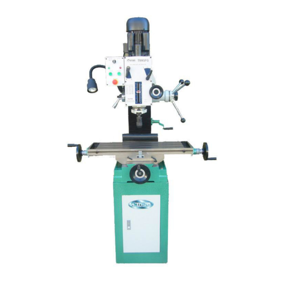
- Page 1 OPERATION MANUAL TM45FG TITAN MACHINERY CO., LTD. www. Titanmachinery.com.cn...
- Page 2 1. In order to safety operate the machine please read the instruction manual seriously especially the “ Safety Items ” before installation and operation otherwise running machine is not allowed. 2. The machine was manufacturered according to the following standards: EN13128-2001:《Safety of machines-Milling machines(including boring machine)》;...
- Page 3 ENVIRONMENTAL PROTECTION NOTICE Following instructions should be abided when machine have to be scrapped finally: 1、 The poisonous, harmful article or un-degradated waste materials and other waste electric components which can not be re-used should be sent to the designated place to deal with.
-
Page 4: Safety Items
1. SAFETY ITEMS 1.BASIC SAFETY ITEMS ▲ DANGER! 1.1The electric system should have good earth, the yellow and green leads should not less than 2.5mm 。 The required earth line which import power supply general earth terminal are muti-ply yellow/green soft wires which≥4mm ,and connect to copper bar. - Page 5 ▲ WARNING! 1.7 Do not touch the rotating workpiece and tools. 1.8 Check moving parts of machine and make sure the safety guard is reliable before power connection. ▲ NOTE! 1.9 Un-specific person cannot open the electric box to repair the electrical equipment.
- Page 6 2.6 Do not use the wet hand to touch the electric components otherwise the created short-circuit will cause personal injury. 2.7 Turn the feed switch button to the (OFF),and turn the feed control button to(0) when tapping。 2.8 Adjust flow of coolant under the circumstance of stopping. 2.9 Do not wear gloves when operating machine.
- Page 7 ▲ NOTE! 2.16 Timely lubricate the machine according to the instruction manual. 2.17Suggest not running the machine during the thunder weather. 2.18 If you want to leave for a while shut off the power supply switch on the operation panel and the main power supply switch after finishing procession.
- Page 8 ▲ NOTE! 3.7 The changed electric components should be same with the original one. 3.8 Put the removed parts far away from the machine to keep safety. 4、SAFETYGUARD POINTS FOR ATTENTION ▲ DANGER! 4.1 Stop machine when cleaning。 ▲ WRNING! 4.2 Change the easy damaged parts according to the manual.
- Page 9 1. MAIN STRUCTURE AND FEATURES The machine is consist of base, column, cross table, spindle box, motor and etc. The spindle can get 6 to 12 speeds by the motor through gear transmission of each axis. Strong structure of spindle may install many kinds of tools to process and the spindle sleeve is equipped with lock device which make the positioning more reliable.
- Page 10 DIA.1 Dia.1 1、TRANSPORTION Machine sends to the customer with solid packing. Please pay attention to the marks (especially the rope position and center...
- Page 11 position), do not place upside down, incline, put crosswise and shock the machine when lifting. Because the bottom area of packing is small and machine is higher we suggest use crane or forklift to transport. NOTE:MACHINE GROSS WEIGHT 350KG Please use forklift before removing packing (as Dia.1) .Open the packing and check the accessories then put the machine on the installation foundation.
- Page 12 Use the firm ropes to lift machine and keep balance when moving(as Dia.2). 图 2 Dia.2...
- Page 13 The smallest site area of this machine is the circle area which table moves one circle around the column. Please consider the work piece, tool box, accessories area, operation space, maintaenance space (as Dia. 4) when machine taking its’ place. Too close to the wall , other machines or objects is un-easy and un-safe.。...
-
Page 14: Main Technical Parameter
5.MAIN TECHNICAL PARAMETER Model cast iron 45mm Drilling mild steel 32mm capacity Face mill capacity 80mm End mill capacity 32mm Working table size 800mm×240mm Working table cross travel 175mm Working table longitudinal 560mm travel T-Slot size 14mm Head tilt left right 90°... -
Page 15: Machine Lubrication
MACHINE LUBRICATION The transmission box of this machine is applied with sealed type rolling bearing which no need to lubricate. Bearings installed on the cross table need to be manually lubricated as Dia.5 showed follow: Dia.5 (1)Spindle transmission parts need to be lubricated twice a year with high grade lubricant. -
Page 16: Machine Adjustment
lubricant. There is an oil cup on the worm gear, oiling twice every shift. (3)To make the machine operating more flexible ,oil film should be formed on the spindle sleeve and the surface of column to prevent rust and stop dust. (4)The return spring should be lubricated once a year. -
Page 17: Machine Operation
(3)Adjustment of cross table backlash and wear compensation a.The wedge installed on the cross slide to adjust backlash of table and perform wear compensation. b. When backlash is big, clock wise turning the bolt on the cross slide and when backlash is small adjust a little on the contrary.。 c. - Page 18 When need auto tapping, turn the knob to the tapping position, rotate the feed handle to the required depth, adjust to the proper speed then start tapping. When the tap reaches the controlled depth, the spindle will return back to the original position.
- Page 19 handle, draw the operation handle to the left and return to the original position by the worm shaped spring. (4)When performing cross milling, rotate the two screws on the right side of cross slide to lock longitudinal movement, as Dia.8. (5)When performing longitudinal milling, rotate the two screws in front of cross slide to lock cross movement, as Dia.9.
- Page 20 TOOL CHANGING (1)The tail of twist drill insert into the flat slot in the spindle hole, check the drill installation then start operation. When removing the twist drill, put the small end of tool back wedge to the top of tail in the spindle tool back hole from tool back hole lies in the right side of spindle sleeve, hole the drill with left hand then knock the big end of tool back wedge lightly, tool will be taken out.
-
Page 21: Electric System
10.TAPPING EQUIPMENT This machine can be equipped with an equipped with an electrics switch tapping operation clockwise counter-clockwise, and the working depth also can be adjusted by the limit switch.(Electric switch will be installed according to your requirement, and you must pay the cost only.) ELECTRIC SYSTEM... -
Page 22: Points For Attention
POINTS FOR ATTENTION... -
Page 23: Troubleshooting
(1)Do not exceed the Max. processing capacity and allowed cutting range when operating machine, over-load cutting is forbidden also. (2)Stop the machine before changing speed. (3)Timely oiling and lubricate according to the lubrication request. (4)Stop the machine and check immediately when troubles or abnormal voice happen. - Page 24 TROUBLE PROBABLE CAUSE REMEDY Excessive 1.Motor out of balance 1.Balance or replace problem motor. Vibration 2.Bad motor 2.Replace motor Motor stalls 1.Over feeding. 1.Reduce feed rate. 2.Dull drill. 2.Sharpen drill and keep sharp. 3.Motor not building up to 3.Replace or repair motor. Check fuses in all running speed three legs on three phase motors and replace if necessary.
-
Page 26: Headstock Assembly
HEADSTOCK ASSEMBLY PART NO. DESCRIPTION JB/T7273.2-94 Handle M6*32 JB/T7270.4-94 Handqheel 12*100 GB/T77-85 Screw M5*8 XZ32G-30-011 Dial seat GB/T70-85 Screw M6*14 GB/T70-85 Screw M5*14 XZ32G-30-009 Cover XZ32G-30-008 Bearing spacer GB/T276-94 Bearing 6202 XZ32G-30-007 worm shaft JB/T7271.1-94 Ball knob M12*40 JB/T7271.6-94 Handle lever BM12*160 XZ32G-30-006 Lock bolt with knob XZ32G-30-004... - Page 27 XZ32G-20-032 Oil filler plug XZ32G-20-012 Head body cover GB/T118-86 Taper pin 10*50 GB/T1096-79 Key 6*35 Motor GB/T96-87 Washer 8 GB/T5781-86 Screw M8*25 XZ32G-20-014 Arbor bolt cover XZ32G-20-016 GB/T70-85 Screw M8*55 GB/T893.1-86 Reainer 35 GB/T276-94 Bearing 6202 GB/T894.1-86 Inner ring 18 XZ32G-20-020 Gear GB/T2089-84...
- Page 28 GB/T1096-79 Key 6*18 GB/T9877.1-88 Oil seal B35*45*10 GB/T70-85 Screw M5*14 XZ32G-20-008 Lever XZ32G-20-009 Gasket ring XZ32G-20-038 Screw knob XZ32G-20-039 Washer XZ32G-20-036 Spring cover XZ32G-20-037 Spring GB/T70-85 Screw M5*10 XZ32G-20-040 Spring base XZ32G-20-042 Lock handle GB/T77-85 Screw M10*10 GB/T79-85 Screw M10*25 XZ32G-20-041A Fixed tight collar A XZ32G-20-041B...
- Page 30 TABLE ASSEMBLY PART No. DESCRIPTION QTY. GB/T7270.4 Handle BM10×80 XZ32G-10-001 Hand wheel GB/T73-85 Screw M6×10 XZ32G-10-002 Dial clutch GB/T879-86 Spring pin 5×40 XZ32G-10-044 Dial ring GB/T70-85 Screw M8×16 XZ32G-10-003 Square flange GB/T118-86 Taper pin 8×30 JB/T7940.4-95 Oil cup GB/T301-94 Thrust bearing 51103 XZ32G-10-004 Cross Lead Screw XZ32G-10-005...
- Page 31 XZ32G-10-043 Moveable fixed block XZ32G-10-012(2) Handle XZ32G-10-012(1) Lock screw XZ32G-10-020 XZ32G-10-014 Center base GB/T119-86 Pin 8×20 XZ32G-10-021 Support XZ32G-10-041 Connective plate XZ32G-10-032 Taper gear GB/T276-94 Bearing 6204-2RS GB/T894.1-86 Retain ring 20 GB/T1096-79 Key 5×12 XZ32G-10-022 Screw GB/T67-85 Screw M5×10 XZ32G-10-039 Cover GB/T70-85 Screw M8×40...
Need help?
Do you have a question about the TM45FG and is the answer not in the manual?
Questions and answers