Sign In
Upload
Manuals
Brands
Phytec Manuals
Computer Hardware
phyCORE-AM335 Series
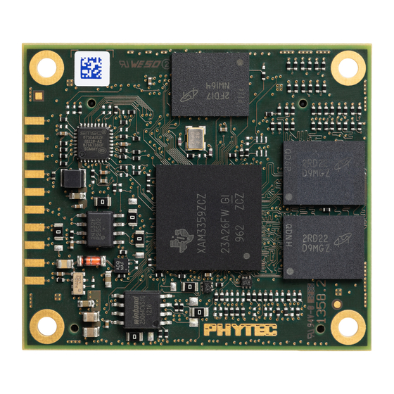
User Manuals: Phytec phyCORE-AM335 Series Module
Manuals and User Guides for Phytec phyCORE-AM335 Series Module. We have
1
Phytec phyCORE-AM335 Series Module manual available for free PDF download: Hardware Manual
Phytec phyCORE-AM335 Series Hardware Manual (101 pages)
Brand:
Phytec
| Category:
Computer Hardware
| Size: 8 MB
Table of Contents
Table of Contents
3
Conventions, Abbreviations and Acronyms
11
Preface
14
1 Part I: PCM-051/Phycore-Am335X System on Module
15
Introduction
15
1Block Diagram
16
Figure 1: Block Diagram of the Phycore-Am335X
16
2View of the Phycore-Am335X
17
Figure 2: Top View of the Phycore-Am335X (Controller Side)
17
Figure 3: Bottom View of the Phycore-Am335X (Connector Side)
18
3Minimum Requirements to Operate the Phycore-Am335X
19
Phycore Connectors and Pins
20
Figure 4: Phycore Pinout Viewed through the Top of the SOM
20
Table 1: Pinout of the Phycore-Connector X1, Row a
22
Table 2: Pinout of the Phycore-Connector X1, Row B
24
Table 3: Pinout of the Phycore-Connector X3, Row a
27
Table 4: Pinout of the Phycore-Connector X3, Row B
30
Jumpers
32
Figure 5: Jumper Locations (Top View)
33
Table 5: SOM Jumper Settings
34
Power
36
1Primary System Power (VDD_5V_IN)
36
2Optional Backup Power (VBAT_IN_4RTC)
36
3Power Management IC (U4)
37
Figure 6: Am335X SOM Power Scheme
37
Backup Battery Management
38
Real-Time Clock (RTC)
39
System Configuration and Booting
40
Table 6: Boot Device Order of Am335X Module 1
40
System Memory
41
1Ddr3-Sdram (U7, U9)
41
2NAND Flash Memory (U10)
41
3SPI Flash Memory (U5)
41
C Eeprom (U6)
41
EEPROM Write Protection Control (J9)
42
Setting the EEPROM Lower Address Bits (J7, J8)
42
5Memory Model
42
Table 7: U6 EEPROM I²C Address Via J7 and J8
42
Table 8: EEPROM Write Protection States Via J9 1
42
SD / MMC Card Interfaces
43
Table 9: Locations of Named SD/MMC0 Card Interface Signals on Phycore Connector X3
43
Serial Interfaces
44
1Universal Asynchronous Receiver/Transmitter Interfaces (Uarts)
44
2USB-OTG Interfaces
45
Table 10: Locations of the UART Signals
45
Table 11: Location of the USB-OTG Signals on the Phycore Connectors
45
3Ethernet1 with PHY (U3)
46
Table 12: Ethernet1 Signals
46
4Ethernet 2
47
5Profibus
47
C Interface
47
Table 13: Location of the Ethernet 2 Signals
47
7SPI Interfaces
48
Table 14: I²C Interface Signal Locations
48
Table 15: SPI Interface Signal Locations
48
8Controller Area Network (CAN) Interfaces
49
9Multichannel Audio Serial Ports (Mcasp)
49
Table 16: Mcasp Signal Locations
49
General Purpose I/Os
50
Table 17: Locations of Dedicated GPIO Pins
50
JTAG / Debug Interface (X2)
51
Figure 7: JTAG Interface at X2 (Top View)
51
Table 18: JTAG Connector X2 Signal Assignments
52
Table 19: Location of JTAG Pins on Phycore Connector X1
52
Display Interface
53
1Parallel Display Interface
53
Table 20: Parallel Display Interface Signal Locations
53
2Touch Screen Controller
54
Technical Specifications
55
Figure 8: Physical Dimensions
55
Handling the Phycore-Am335X
57
Component Placement Diagram
58
Figure 9: Phycore-Am335X Component Placement (Top View)
58
Figure 10: Phycore-Am335X Component Placement (Bottom View)
59
2 Part II: PCM-953 / Phycore-Am335X Carrier Board
61
The Phycore-Am335X SOM on the Phycore-Am335X Carrier Board
61
1Phycore-Am335X Carrier Board Power
62
Figure 11: +5 VDC Power Input Connector
62
2Overview of the Phycore-Am335X Carrier Board Peripherals
63
Figure 12: Phycore-Am335X Carrier Board Overview of Connectors and Buttons (Top View)
63
Connectors and Pin Headers
64
Table 21: Phycore-Am335X Carrier Board Connectors and Pin Headers
64
Buttons
65
Figure 13: Carrier Board Buttons
65
Figure 14: Carrier Board Leds
66
Leds
66
Table 22: Phycore-Am335X Carrier Board Push Buttons Descriptions
66
Jumpers
67
Table 23: Phycore-Am335X Carrier Board Leds Descriptions
67
Figure 15: Carrier Board Jumper Locations
68
Figure 16: Jumper Numbering Scheme
68
Table 24: Phycore-Am335X Carrier Board Jumper Descriptions
69
Carrier-Board Boot-Configuration Switch S5
71
Figure 17: Switch S5 Location
71
Carrier Board Bus Switches
72
Table 25: Carrier Board Boot Configuration Switch S5
72
Figure 18: Bus Enable Jumpers and Leds
73
Table 26: How to Configure Bus Switch Enable Signals with JP3 and JP4
73
Table 27: Which Interfaces Are Enabled with Which JP3 and JP4 Signal Settings
73
Ethernet 1 (X12)
74
Figure 19: Ethernet1 Connector
74
Table 28: Bus Switch Enable Status Leds
74
Ethernet 2 (X9)
76
Figure 20: Ethernet 2 Connector
76
Ethercat 0 and 1 (X10 and X11)
77
Figure 21: Ethercat Connectors
77
10Profibus (X19)
78
Figure 22: Profibus Connector
78
11Rs-232 (X18)
79
Figure 23: RS-232 Connector
79
12Can (X13)
80
Figure 24: CAN Connector
80
13USB (X7 and X8)
81
Figure 25: USB Connectors and Jumpers
81
Table 29: USB Connectors for Different Operating Modes
82
14Spi (X5)
83
Figure 26: X5 GPIO Expansion Board Connectors
83
15Jtag (X21)
84
Figure 27: JTAG Connector
84
Table 30: Carrier Board JTAG Connector X21
85
16Display / Touch (X4)
86
Figure 28: Display Connectors
86
16.1Parallel Display Interface Connector (X4)
87
Table 31: PDI Connector X4 Signal Description
87
16.2PDI Power Connector (X31)
89
Table 32: Auxiliary Interfaces at LVDS Display Connector X4
89
Table 33: PDI Power Connector X31 Signal Description
89
17Mmc/Sd (X20)
90
Figure 29: MMC/SD Connector
90
18Mcasp (X14, X15, X16, X17)
91
Figure 30: Audio Connectors
91
Table 34: Audio Connectors
91
Table 35: Audio Hardware Configuration Jumpers
92
19Wifi (X27)
93
Figure 31: Wifi Connector
93
3 Part III: PCM-957 GPIO Expansion Board
95
GPIO Expansion Board Analog Signals
95
GPIO Expansion Board Control Signals
95
Table 36: GPIO Expansion Board Analog Signal Map
95
Table 37: GPIO Expansion Board Control Signal Map
95
GPIO Expansion Board GPIO Signals
96
GPIO Expansion Board GPMC Signals
96
Table 38: GPIO Expansion Board GPIO Signal Map
96
Table 39: GPIO Expansion Board GPMC Signal Map
96
GPIO Expansion Board Power Signals
97
GPIO Expansion Board Serial Interfaces
97
Table 40: GPIO Expansion Board Power Signal Map
97
Table 41: GPIO Expansion Board Serial Interfaces Signal Map
97
Signals Not Connected to the GPIO Expansion Board
99
Table 42: Am335X SOM Signals Not Routed to the GPIO Expansion Connector X5
99
Advertisement
Advertisement
Related Products
Phytec phyCORE-AM62Ax
Phytec phyCORE-MPC5676/57 Series
Phytec phyCORE-DS80C390
Phytec phyCORE-i.MX 8M Plus
Phytec ATOM phyCORE-Z500P(T)
Phytec phyCORE-PXAG49
Phytec phyCORE-TC399
Phytec phyCORE-167
Phytec phyCORE-Vybrid
Phytec phyCORE-XAGx
Phytec Categories
Computer Hardware
Motherboard
Single board computers
Microcontrollers
Control Unit
More Phytec Manuals
Login
Sign In
OR
Sign in with Facebook
Sign in with Google
Upload manual
Upload from disk
Upload from URL