Table of Contents
Advertisement
Advertisement
Table of Contents

Related Manuals for Erbe ERBOTOM ICC 350


Summary of Contents for Erbe ERBOTOM ICC 350
- Page 1 ERBE ERBOTOM ICC 350 Instruction manual 08.00...
- Page 3 ERBOTOM ICC 350 V 4.X 10128-016, 10128-061, 10128-300, 10128-301, 10128-025,10128-402 ERBOTOM ICC 350 Z V 2.X 10128-065 ERBOTOM ICC 350 T V 2.X 10128-066 ERBOTOM ICC 350 M V 4.X 10128-080, 10128-083 ERBOTOM ICC 350 M-DOKU V 4.X 10128-081 Instruction manual...
- Page 4 ERBE ELEKTROMEDIZIN GmbH. The information contained in this instruction manual may be revised or extended without prior notice and represents no obligation on the part of ERBE ELEKTROMEDIZIN GmbH. © ERBE ELEKTROMEDIZIN GmbH, Tübingen 2000 Printed by: ERBE ELEKTROMEDIZIN, Tübingen...
-
Page 5: Table Of Contents
Chapter Title Page INTRODUCTION..............1-1 Intended purpose of the ICC 350 ..........1-1 How do I work with this instruction manual? ......1-1 Explanation of the safety instructions ......... 1-1 INITIAL OPERATION ............2-1 RISKS AND SAFETY OF HIGH-FREQUENCY SURGERY ........3-1 Unintentional thermal tissue damage .......... - Page 6 ERBOTOM ICC 350 Z ............5-1 ERBOTOM ICC 350 T ............6-1 ERBOTOM ICC 350 M ............7-1 ERBOTOM ICC 350 M-DOKU ........... 8-1 TECHNICAL DATA, SIGNALS, DIAGRAMS..... 9-1 Technical data ................9-1 Visual and acoustic signals ............9-5 Diagrams ..................9-6 INSTALLATION ...............
-
Page 7: Introduction
INTRODUCTION Intended purpose of the ICC 350 The ICC 350 is a high-frequency surgical unit for cutting and coagulation. Due to its performance features, it has universal applications. To meet the special requirements of surgical specialty fields, the ICC 350 is available in several versions. How do I work with this instruction manual? Please read the instruction manual for the ICC 350. -
Page 9: Initial Operation
INITIAL OPERATION Read carefully before initial operation of the unit. In the development and production of this high-frequency surgical unit, the relevant, generally recognized rules of technology, as well as the valid occupational safety and accident prevention regulations have been taken into consideration. This ensures that patients, employees and third parties are protected from dangers to life and health during intended application of the high- frequency surgical unit, to the extent permitted by the type of application intended. -
Page 11: Risks And Safety Of High-Frequency Surgery
RISKS AND SAFETY OF HIGH-FREQUENCY SURGERY Unintentional thermal tissue damage High-frequency surgery is associated in principle with various risks for the patient, the personnel and surroundings. In order to avoid these risks in practice, the surgeon and his/her assistants must recognize these risks and observe the appropriate rules for prevention of damage. In the following, these risks and rules for prevention of damage are explained. - Page 12 3.1.2 Unintentional activation of an HF generator Unintentional activation of an HF generator can lead to burns on the patient if the active electrode hereby touches the patient directly or indirectly through electrically conductive objects or wet cloths. Unintentional activation of an HF generator can, for example, be caused by: Ÿ...
-
Page 13: The Neutral Electrode
3.1.3 Unintentional thermal tissue damage due to inappropriate application Generally speaking, the bipolar coagulation technique should be applied in preference to the monopolar coagulation technique. This particularly applies to coagulations on straight organs, on which the high-frequency current flows over longer areas through diameters which are approximately equal or become even smaller. - Page 14 WARNING The effective contact surface, i.e. the electrical conductive value between the neutral electrode and the patient must correspond to the HF capacity used, meaning the intensity of the HF current. Here the effective contact surface means the surface of the neutral electrode which has electrically conductive contact to the skin of the patient during high-frequency surgery.
- Page 15 3.1.6 Unintentional thermal tissue damage due to inattentiveness Like a scalpel, high-frequency surgery is always a potential source of danger if handled without care. WARNING The cutting or coagulation electrodes should always be handled with care and laid aside in the intervals between use so that neither the patient nor other persons can come in contact with the electrodes.
-
Page 16: 3.1.9 Unintentional Burns Due To Hot Electrodes
WARNING Make certain during high-frequency surgical operations that anesthetics, skin cleaning agents and disinfectants are nonflammable. If their use is unavoidable, they must have completely evaporated and the vapor must be removed from the area of spark formation before switching on the high-frequency surgical unit. -
Page 17: Cardiac Pacemaker
During cutting procedures, forced coagulation and spray coagulation, the unavoidable electric arcs between an active electrode and the tissue nevertheless have the effect that a portion of the high-frequency alternating current is rectified, from which more or less strongly modulated, low-frequency current components result which stimulate electrically stimulable structures such as nerves and muscles. - Page 19 Standard International...
-
Page 21: Description Of The High-Frequency Surgical Unit
Monopolar and bipolar cutting modes With the ERBOTOM ICC 350, both monopolar and bipolar cutting electrodes can be operated. A special operating mode is available for the users of bipolar cutting electrodes, which can be called up as program “b“. - Page 22 ENDO CUT A further special problem during endoscopic operations, for example during polypectomy and papillotomy, consists in the fact that the electrodes used for cutting, for example polypectomy loops and papillotomes, must be guided on long wire pulls through narrow working channels on flexible endoscopes, and therefore the operator has no direct control over the cutting procedure.
- Page 23 The footswitch or Auto Start is used for activation. In the Auto Start mode, the HF generator is automatically activated if both poles of the bipolar coagulation instruments used contact electrically conductive tissue simultaneously. Auto Start can occur either immediately at the moment of contact with the tissue or more or less temporally delayed.
-
Page 24: Description Of The Controls
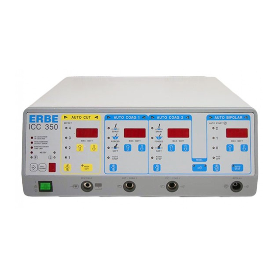
Description of the controls This symbol, in accordance with EN 60 601-1, is intended to indicate to the user that this unit must only be used on the patient if the user is acquainted with the operation and features of this unit. The figures set in cursive relate to the ICC illustration for this chapter, or to the function fields in the text. -
Page 25: Auto Cut Function Field
AUTO CUT function field All parameters can be set in this function field that are relevant to cutting: 2.1 Setting of the coagulation EFFECT when cutting Here the required cutting quality in regard to the coagulation effect on the cutting edges can be adjusted. -
Page 26: Auto Coag 1 Function Field
AUTO COAG 1 function field All parameters can be set in this function field and are relevant to monopolar coagulation: Selection of the coagulation mode By pressing this key, one of the following coagulation modes can be selected: Soft coagulation without Auto Stop Forced coagulation (Check the version. -
Page 27: Auto Coag 2 Function Field
AUTO COAG 2 function field All parameters can be set in this function field and are relevant to monopolar coagulation: Selection of the coagulation mode By pressing this key, one of the following coagulation modes can be selected: Soft coagulation without Auto Stop 4.2.1 Soft coagulation with Auto Stop Forced coagulation (Check the version. -
Page 28: Auto Bipolar Function Field
If you nevertheless wish to use the AUTO START function, please consult your local ERBE branch office. You will find the address on the last page of the Instruction Manual. Technical Service will activate the AUTO START function for you on request. -
Page 29: Working With Programs
The basic setting for program “0“ is defined and programmed by the manufacturer and cannot be reprogrammed by the user. For the ERBOTOM ICC 350, Software Version 1.05 and up, the basic setting for program “0“ is defined and stored as follows: AUTO CUT: Auto. - Page 30 setting is also to be used for the following operations, it can be accepted into this program. To do this, only the SAVE key 6.1 must be depressed uninterruptedly long enough until “Set“ is indicated on display 3.6 for Auto Coag 1 and the signal heard continuously during storage changes into an intermittent signal.
- Page 31 The ERBOTOM ICC 350 is also equipped in the ENDO CUT mode with an automatic initial incision control which recognizes low-resistance loads and controls the HF generator in such a way that it briefly provides enough power so that the initial incision can proceed without delay.
-
Page 32: Connecting Socket For Neutral Electrodes
The ERBOTOM ICC 350 is equipped with a Neutral Electrode Safety System (NESSY) which automatically monitors the electrical connection between the neutral electrode and the unit as well as application of the neutral electrode on the patient. -
Page 33: Connecting Socket For The Auto Bipolar Function Field
WARNING For simultaneous connection of two electrode handles to both monopolar connecting sockets 8 and 9, electrode handles (particularly if they look alike) must be laid down in such a way that there can be no mix-up. In case of doubt, a trial activation of the unit should be performed without contacting the patient with the active electrode. -
Page 34: Terminal For Potential Equalization
Terminal for potential equalization For this, see Chapter 10.4, INSTALLATION. Volume of the acoustic signal The volume of the acoustic signals can be adjusted with this knob. This does not apply to warning signals, which must always be sufficiently loud. WARNING An important purpose of this acoustic signal is to protect the patients and personnel from burns due to unintentional activation of the high-frequency generator (for more information, see Chapter... -
Page 35: Description Of The Safety Features
LF leakage current to less than 0.05 mA. This error is indicated visually as Error no. 5 and acoustically. The HF generator can only be activated once the cause of error has been eliminated. In this way, the ERBOTOM ICC 350 also fulfills the Type CF requirements in the Earth Referenced mode. - Page 36 In practice, despite careful positioning of the patient on the operating table, unintentional contact of the patient with electrically conductive objets can occur. In some operations, such contacts are unavoidable. The ICC is therefore equipped with an HF leakage monitor, which automatically monitors the HF leakage current and generates a visible warning signal if the HF leakage exceeds 150 mA If the HF leakage current exceeds 300 mA , the HF leakage monitor additionally produces an...
- Page 37 Custom adaptation of the maximum time limit In consideration of the risk of thermal tissue damage due to unintentional switching on of an HF generator, an unintentionally switched-on HF generator should be switched off again as soon as possible automatically. Since the unit cannot automatically distinguish between intentional and unintentional switching on of an HF generator, the automatic switching off of an HF generator must not occur too quickly, because this would hinder the operator during cutting and/or coagulation.
- Page 38 NESSY is a flexible Neutral Electrode Safety System that can be adapted optimally to the neutral electrodes selected by the user. For appropriate advice and adaptation to suit requirements, please contact your local Erbe office (see Chapter Addresses). 4-18...
- Page 39 WARNING For reasons of safety, a change to NESSY may only be made if it has been properly ensured that all users of this unit are informed in good time about this change. In addition, a change to NESSY must be properly documented. When using dual-surface neutral electrodes, NESSY also monitors the application direction of the contact surface relative to the direction of current flow.
- Page 40 Correct application The correct application must be observed not only for divided, but also for undivided neutral electrodes. WARNING Before the neutral electrode is applied to the patient’s body, a check must be made as to whether the green NESSY signal (LED) does not light when using a neutral electrode with two contact surfaces.
- Page 41 You may connect three instruments at the same time to the ICC. For reasons of safety, these can however only be used alternately. Only one socket ever carries HF voltage. Each time after switching on the power switch, an automatic test program is started within the unit which recognizes and signals the following errors in the operating controls for the unit and for accessories connected to the unit: If a key on the front panel is shorted or pressed due to an error when the power switch is...
- Page 42 4-22...
-
Page 43: Erbotom Icc 350 Z
ERBOTOM ICC 350 Z Intended use The ERBOTOM ICC 350 Z is equipped with a Neurotest device which is used to localize electrically excitable tissue structures. Additional controls Connecting socket for the active Neurotest electrode on the front panel To prevent a mix-up of the electrode handles for high-frequency surgery and the electrode handle for the Neurotest device, electrode handles no. - Page 44 Operation Basics The NEUROTEST device in the ERBOTOM ICC 350 Z is used for intraoperative differentiation of electrically stimulable tissue structures, for example the facial nerve, during surgical operations in dental, oral and maxillofacial medicine (DOM). Here, an electric stimulation in the form of periodical current pulses is applied to the tissue to be differentiated and any reaction of the stimulated muscle is observed.
- Page 45 Safety of the NEUROTEST device The following safety-related functions of the NEUROTEST device in the ERBOTOM ICC 350 Z are automatically monitored: When activating the NEUROTEST device, a test is first made as to whether a neutral electrode is connected to the unit and to the patient (the latter only if a neutral electrode with two contact surfaces is used).
- Page 46 After 80 seconds of uninterrupted activity, the “time limit” visual signal is illuminated and after a further 10 seconds, the Neurotest device is automatically deactivated. However, the Neurotest device can be immediately reactivated after this. Technical data NEUROTEST device in the ERBOTOM ICC 350 T Pulse waveform square Pulse duration 0.33 ms...
-
Page 47: Erbotom Icc 350 T
ERBOTOM ICC 350 T Intended use The ERBOTOM ICC 350 T is equipped with a Neurotest device which is used to localize electrically excitable tissue structures. Additional controls Connecting socket for the active Neurotest electrode on the front panel Electrode handles for cutting and coagulation are also connected to this socket. - Page 48 Operation Basics The NEUROTEST device in the ERBOTOM ICC 350 Z is used for intraoperative differentiation of electrically stimulable tissue structures, for example the external sphincter during transurethral resections (TUR) of the prostate. Here, an electric stimulation in the form of periodical current pulses is applied to the tissue to be differentiated and any reaction of the stimulated muscle is observed.
- Page 49 Safety of the NEUROTEST device The following safety-related functions of the NEUROTEST device in the ERBOTOM ICC 350 T are automatically monitored: When activating the NEUROTEST device, a test is first made as to whether a neutral electrode is connected to the unit and to the patient (the latter only if a neutral electrode with two contact surfaces is used).
- Page 50 After 80 seconds of uninterrupted activity, the “time limit” visual signal is illuminated and after a further 10 seconds, the Neurotest device is automatically deactivated. However, the Neurotest device can be immediately reactivated after this. Technical data NEUROTEST device in the ERBOTOM ICC 350 T Pulse waveform square Pulse duration...
-
Page 51: Erbotom Icc 350 M
ERBOTOM ICC 350 M Intended use As a complement to the ICC 350, the ERBOTOM ICC 350 M is intended for the operation of multifunctional instruments with pneumatic actuator and MIN instruments. For this, it is equipped with the programs C = MIC (minimally invasive surgery) and n = MIN (minimally invasive neurosurgery) and additional controls. - Page 52 Erbotom ICC 350 M Installation Connect the ERBOTOM ICC 350 M to a compressed air source with 5 +/- 1 bar. As a compressed air source, the central compressed air supply of the OR can be used. To connect the ERBOTOM ICC 350 M to the standard gas supply outlet according to DIN 13 260 Part 2 in the operating room, use one of the following ERBE compressed air tubes: ERBE compressed air tube, 5 m long, Article No.
- Page 53 Luer-lock caps. Connect the multifunctional instrument to the ERBOTOM ICC 350 M. The ERBOTOM ICC 350 M is equipped with an Instrument Identification System (IIS). As soon as a multifunctional instrument is connected to the MIC socket (19), the IIS automatically checks which instrument it is and briefly displays the code number of the respective instrument.
- Page 54 Program n = MIN (Minimally Invasive Neurosurgery) The “n” program is intended for operating MIN probes on the MIC connecting socket. In this program, the parameters for these probes can be set. Functions that are irrelevant or even impermissible for the operation of such instruments are limited or switched off according to the instrument.
-
Page 55: Erbotom Icc 350 M-Doku
ERBOTOM ICC 350 M-DOKU Intended use As a supplement to the ICC 350, the ERBOTOM ICC 350 M-DOKU is intended for the operation of multifunctional instruments with pneumatic actuator and MIN instruments. For this, it is equipped with the programs C = MIC (minimally invasive surgery) and n = MIN (minimally invasive neurosurgery) and additional controls. - Page 56 The length of the optical waveguide cable is sufficient to connect the optical waveguide box to the ICC 350 M-DOKU. The computer and the plug-in power supply unit for the optical waveguide box are supplied with system voltage via a permanently installed power outlet. The ICC 350 is supplied with system voltage via another permanently installed power outlet.
- Page 57 Protocol parameters Baud rate: 19,200 Start bit: Data bit: Stop bit: Parity: even, no Software installation Two files are provided, ICC3.EXE and EGAVGA.BGI. EGAVGA: graphic driver. ICC3.EXE: ICC 350 documentation program. Program start with ICC3.exe IMPORTANT The program only runs reliably in DOS. ICC 350 incision image program The activation time for the incision image registration is 32 seconds max..
- Page 58 F4: Display diagram power ON or OFF. The actual power is calculated from current, voltage and cos f.. F5: Display diagram phase shifting ON or OFF. Phase shifting between voltage and current from 0..90 degrees. 0 degrees: actual. 90 degrees: capacitive. F6: Display diagram spark measurement value ON or OFF.
-
Page 59: Technical Data, Signals, Diagrams
TECHNICAL DATA, SIGNALS, DIAGRAMS Technical data Cutting, monopolar with automatic voltage control (AUTO CUT) HF voltage waveform unmodulated sinusoidal alternating voltage Crest factor C, at R = 500 ohms C = 1.4 for all setttings Rated frequency 330 kHz Maximum HF voltage at load resistance RL = ∞ 650 V Dynamic internal impedance in rated load range 0 ohm... - Page 60 CUTTING / ENDO CUT Automatic arc-triggered, fractionated incision Basic setting = 50 ms, = 750 ms Soft coagulation (SOFT COAG) HF voltage waveform unmodulated sinusoidal alternating voltage Crest factor C, at R = 500 ohms C = 1.4 for all setttings Rated frequency of the HF voltage 330 kHz Peak value of the HF voltage...
- Page 61 Bipolar coagulation (AUTO BIPOLAR) HF voltage waveform unmodulated sinusoidal alternating voltage Crest factor C, at R =500 ohms C = 1.4 for all settings Rated frequency 330 kHz Peak value of the HF voltage 190 V P max Constancy of the HF voltage at RL > 50 ohms automatically controlled HF rated power 120 watts at 125 ohms...
- Page 62 Documentation Automatic storage of operating errors Automatic storage of function errors Automatic storage of safety errors Power connection Rated power voltage 240 V / 230 V / 115 V / 110 V / 100 V ± 10 % Rated power frequency 50 / 60 Hz Power current 4.0 A at 230 - 240 V / 8.0 A at 100 - 115 V...
-
Page 63: Visual And Acoustic Signals
Visual and acoustic signals STATUS visual acoustic HF off • Power switch on •• •• •• Operating error on the front panel •• •• HF generator on •• •• •• LF leakage current greater than 0.05 mA Error No.5 •• red HF leakage current greater than 150 mA, but less than 300 mA ••... -
Page 64: Diagrams
Diagrams AUTO CUT MODE, Effect 1, 2, 3, 4 BIPOLAR CUT MODE Peak value of the HF output voltage U at no load, as a function of the power limitation P for EFFECT 1 to 4. Power limitation in BIPOLAR CUT MODE... - Page 65 HIGH CUT, Effect 1, 2, 3, 4 Peak value of the HF output voltage U at no load, as a function of the power limitation P for EFFECT 1 to 4.
- Page 66 SOFT COAGULATION AUTO BIPOLAR Peak value of the HF output voltage U at no load, as a function of the power limitation P...
- Page 67 FORCED COAGULATION (For. 4 not ICC 350 T, Z) Peak value of the HF output voltage U at no load, as a function of the power limitation P...
- Page 68 SPRAY COAGULATION Peak value of the HF output voltage U at no load, as a function of the power limitation P 9-10...
- Page 69 CUT MODE, Effect 1, 2, 3, 4 Power output as a function of load resistance for power limitation of 300 watts 9-11...
- Page 70 CUT MODE, Effect 1, 2, 3, 4 Power output as a function of load resistance for power limitation of 150 watts 9-12...
- Page 71 HIGH CUT, Effect 1, 2, 3, 4 Power output as a function of load resistance for power limitation of 300 watts 9-13...
- Page 72 HIGH CUT, Effect 1, 2, 3, 4 Power output as a function of load resistance for power limitation of 150 watts 9-14...
- Page 73 SOFT COAGULATION AUTO BIPOLAR Power output as a function of load resistance for 1) power limitation of 120 watts 2) power limitation of 60 watts 9-15...
- Page 74 FORCED COAGULATION Power output as a function of load resistance for 1) power limitation of 120 watts 2) power limitation of 60 watts 9-16...
- Page 75 SPRAY COAGULATION Power output as a function of load resistance for 1) power limitation of 120 watts 2) power limitation of 60 watts 9-17...
- Page 76 BIPOLAR CUT MODE Power output as a function of load resistance for 1) power limitation of 100 watts 2) power limitation of 50 watts 9-18...
- Page 77 AUTO CUT MODE, Effect 1, 2, 3, 4 Power output as a function of the power limitation = 500 ohms 9-19...
- Page 78 HIGH CUT, Effect 1, 2, 3, 4 Power output as a function of the power limitation = 500 ohms 9-20...
- Page 79 SOFT COAGULATION AUTO BIPOLAR Power output as a function of the power limitation = 125 ohms 9-21...
- Page 80 FORCED COAGULATION Power output as a function of the power limitation = 350 ohms Forced 1, 2, 3, 4 9-22...
- Page 81 SPRAY COAGULATION Power output as a function of the power limitation = 500 ohms 9-23...
- Page 82 NESSY Dependence of the warning signals on contact resistance R between the two contact surfaces of ü a divided neutral electrode and the HF current I flowing through the entire surface of the neutral electrode: A = In this range, I is sufficiently small relative to R .
-
Page 83: Installation
INSTALLATION 10.1 Spatial requirements High-frequency surgery units must only be operated in medically used rooms. The spatial requirements, in regard to electric installation, affect e.g. the grounded conductor system, the ground fault interrupt system, as well as measures for preventing electrostatic charges. The unit is used in rooms in which personnel can pick up electrostatic charges, for example in rooms with electrically nonconductive floors, thus touching the front panel of the units can lead to a brief illumination of light diodes or seven-segment displays due to discharge of an electrostatic... - Page 84 10.6 Protection against moisture ICC model series high-frequency surgical units are protected against the penetration of moisture in accordance with EN 60 601-2-2 . In spite of this, these units should not be set up in the vicinity of hoses or containers which contain liquids. Liquids should not be placed above or even on the unit.
- Page 85 Instructions for custom adaptation of the maximum time limit Call up Test program 10 as follows: Press key 2.1 with the unit switched off and switch on the power. Pr. = Program appears in Display 2.3 The program number, e.g. 1, appears in Display 3.6. By pressing key 3.5 Ý, program no.
- Page 86 10.12 Versions of Forced coagulation For Forced coagulation, the ICC produces brief voltage pulses with a high peak voltage. In this way, an efficient hemostasis is achieved even with very small-surface electrodes, such as with TUR resection loops or laparoscopic retractors. However, these voltage pulses can cause more or less intensive disturbances in other electronic equipment, such as in video monitors.
-
Page 87: Cleaning And Disinfection Of The Unit
CLEANING AND DISINFECTION OF THE UNIT 11.1 Cleaning and disinfection of the unit The unit housing should only be cleaned and disinfected with nonflammable and nonexplosive agents. Make certain here that no moisture penetrates into the unit. We recommend a spray or wipe-down disinfection. However, the information from the disinfectant manufacturer absolutely must be observed here. - Page 88 11-2...
-
Page 89: Performance Checks
PERFORMANCE CHECKS Before every application, the user should check the functional efficiency of the unit and the accessories. The ICC is equipped for this with various automatic performance checks that, each time the power switch is switched on, proceed briefly and thus signal and display recognized errors. -
Page 90: 12.3 Automatic Error Documentation
12.3 Automatic error documentation The ICC is equipped with an automatic error recognition, error signaling and error documentation device. Errors are recorded which are present or occur during the switching on of the power switch, during the Self Check after switching on the power switch, during tests or during activation of the unit and/or of accessories connected to the unit. -
Page 91: Error List
Error list Error Error How to proceed? No error No HF output voltage Notify the Technical Service HF output voltage too high Notify the Technical Service No HF output voltage Notify the Technical Service HF output voltage too high Notify the Technical Service LF leakage current greater than 0.05 mA Notify the Technical Service Activation error... - Page 92 When switching on the power switch, the Check whether there was an operating error or blue pedal on the footswitch or the blue whether the blue key on the electrode handle or the key on the electrode handle was already cable to the electrode handle is defective pressed for CUT/COAG 1 When switching on the power switch, the...
- Page 93 No pulse current Check whether there was an interruption in the connecting cables or whether the active or neutral electrode was not applied No pulse current Check whether there was an interruption in the connecting cables or whether the active or neutral electrode was not applied.
- Page 94 12-6...
-
Page 95: Safety Checks
SAFETY CHECKS To prevent a reduction in safety for the unit due to age, wear etc., § 6 of the regulation concerning the installation, operation and use of active medical products (BetreibVaMP) prescribes regular safety checks. The operator must have the safety checks which have been established for this unit properly performed to the prescribed extent. - Page 96 13-2...
- Page 97 MAINTENANCE, CARE AND DISPOSAL OF THE UNIT 14.1 Maintenance of the unit including reusable accessories Maintenance of the unit including the reusable accessories includes preventive and corrective measures for servicing. Therefore established, regularly performed safety checks (see Chapter 9) represent preventive measures, while changes and repairs can be summarized under the category of corrective maintenance.
- Page 98 14-2...
-
Page 99: Guarantee
Other claims, particularly claims of damage compensation, are excluded. Repair must only be performed by ERBE, one of our representatives, or by an authorized retailer. The claim of guarantee becomes void if improper changes or repairs were made. - Page 100 15-2...
Need help?
Do you have a question about the ERBOTOM ICC 350 and is the answer not in the manual?
Questions and answers