Table of Contents
Advertisement
Advertisement
Table of Contents

Related Manuals for Erbe ICC 200


Summary of Contents for Erbe ICC 200
- Page 1 ERBE ICC 200 ICC 300 H-E ICC 350 09.2004...
- Page 3 ICC 200, ICC 300 H-E, ICC 350 ERVICE MANUAL 10128-002, 10128-009, 10128-010, 10128-015, 10128-016 10128-023, 10128-025, 10128-027, 10128-028, 10128-036 10128-051, 10128-054, 10128-055, 10128-056, 10128-058 10128-061, 10128-064, 10128-065, 10128-066, 10128-070 10128-071, 10128-072, 10128-073, 10128-074, 10128-075 10128-076, 10128-077, 10128-078, 10128-080, 10128-081 10128-082, 10128-083, 10128-200, 10128-202, 10128-204...
- Page 4 ERBE Elektromedizin GmbH. The information contained in this service manual may be revised or extended without prior notice and represents no obligation on the part of ERBE Elektromedizin GmbH. Copyright © ERBE Elektromedizin GmbH, Tübingen 2004 Printed by: ERBE Elektromedizin GmbH, Tübingen...
-
Page 5: Table Of Contents
Calling up Test program mode ............... 10 Basic settings of the SETUP parameters ............11 Front panel of the ICC 200 (INT) after starting up the unit ......12 Front panel of the ICC 200 (UL) after starting up the unit ......13 Front panel of the ICC 300 after starting up the unit ........ - Page 6 / 266...
-
Page 7: Test Programs And Adjustments
Chapter 1 Test programs adjustments... - Page 9 Test programs ERBOTOM ICC 350, 300, 200 Version 4.0 / 3.0 / 2.0 No. Test program function V 4.0 / 3.0 / V 2.0 1 Basic front panel setting (only ICC 300 and 200) 2 Calls up the Error list 3 Test of all D-flipflop circuit memories 4 Test of all front panel visual signals 5 Test of all acoustic signals...
- Page 10 Note regarding the drawing The front panel shown of the ICC 350 applies to the ICC 200 and ICC 300 in such a way that only the AUTO CUT and AUTO COAG control panels apply to the ICC 300, and the AUTO CUT, AUTO COAG and AUTO BIPOLAR control panels apply to the ICC 300.
-
Page 11: Basic Settings Of The Setup Parameters
Remarks ICC 350, ICC 300 adjustable using Test program 23 0.5 s AUTO START delay no stepping 0.5 s ICC 200 Time limit setting output max. time limit ICC 350 Test program 10 Auto Cut 90 s Auto Coag 1... -
Page 12: Front Panel Of The Icc 200 (Int) After Starting Up The Unit
Front panel of the ICC 200 (INT) After starting up the unit Factory setting e f f s t t s t t s t t c t i o l l e f f s t t s t t... -
Page 13: Front Panel Of The Icc 200 (Ul) After Starting Up The Unit
Front panel of the ICC 200 (UL) After starting up the unit Factory programming e f f s t t s t t c t i o l l 1 TEST PROGRAMS AND ADJUSTMENTS / 266... - Page 14 NOTE If the settings are reset, the factory programming of the ICC 200 E and ICC 200 E/A units is lost. It can be restored using the following table. e f f s t t s t t s t t...
-
Page 15: Front Panel Of The Icc 300 After Starting Up The Unit
Front panel of the ICC 300 After starting up the unit Factory setting Basic setting ICC 300 AUTO CUT Effect 3 150 watts max. AUTO COAG SOFT 60 watts max. AUTO BIPOLAR AUTO START = off 60 watts max. Footswitch setting yellow = AUTO CUT blue = AUTO COAG 1 TEST PROGRAMS AND ADJUSTMENTS... -
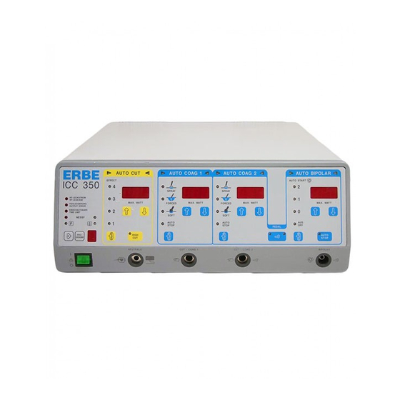
Page 16: Front Panel Of The Icc 350 After Starting Up The Unit
Front panel of the ICC 350 After starting up the unit Factory setting Basic setting ICC 350 AUTO CUT Effect 3 150 watts max. HIGH CUT switched off – AUTO COAG 1 SOFT 60 watts max. AUTO COAG 2 FORCED 60 watts max. -
Page 17: Test Programs 1–8
Test program no. 1 ICC 200, 300 only General description Using this test program, any front panel setting can be made. This setting is known as the basic setting. After termination, the basic setting is stored internally. Only completely saved channels are stored. The basic setting display flashes. - Page 18 Test program no. 2 Call up and display of the error memory General description The ICC units are equipped with a system for error detection, error indication and error memory. Every error receives an error number (ERROR no.). The unit stores the last 10 ERROR numbers. Test program 2 displays the stored ERROR numbers.
- Page 19 AUTO BIPOLAR d0 ... d7 alternating Display (ICC 200) d0 ... d7 alternating (D-FF-Test Nr. 0) tests the external control bus for signal lines d0–d7. The signal lines d0–d7 are switched on and off one after another. The switching statuses can be displayed on the bar graph (adapter board 30183-102).
- Page 20 6 D-FF IC 6 ST power stage 7 D-FF IC 10 Senso-board 8 D-FF IC 8 Relay board not ICC 200 Extension motherboard slot J9 not ICC 200 Extension motherboard slot J9 not ICC 200 Extension motherboard slot J9 not ICC 200...
- Page 21 Test program no. 4 Check of the optical signals on the front panel General description Using this program, you can test the optical displays on the front panel. After starting the test program, you will see the following display: All optical signals on the front panel are switched on. The 7-segment displays show “8.” for all numbers. 1 TEST PROGRAMS AND ADJUSTMENTS / 266...
- Page 22 Test program no. 5 Sound control for all available sounds General description Using this program, you can test and set all available sounds. After starting the program, you will see the following display: Display AUTO CUT AUTO COAG 1 AUTO COAG 2 AUTO BIPOLAR 0 ...
- Page 23 Test program no. 5 Sound control for all available sounds Frequency adjustment for warning tones The warning tone frequency setting can be adjusted independently of other assemblies on the low-voltage power supply (jumper J2) with Test program no. 5. • Activate Test program no.
- Page 24 Rel. 1: Output AE 1 only ICC 300 / 350 Relay board Rel. 2: Output AE 2 only ICC 300 / 350 ICC 200: Mono output Rel. 1: Output AE 1 only ICC 200 board 1 TEST PROGRAMS AND ADJUSTMENTS...
- Page 25 Test program no. 6 Relay test Overview of the relay test options Test no. 0 Switch off all relays Test object Relay status Remarks Power starting Rel. 1, motherboard switched off current limitation all other relays switched off Test no. 1 Switch on all relays Test object Relay status...
- Page 26 Test program no. 7 Setting the NESSY version General description Using this program, you can set four NESSY versions. After starting the test program, you will see the following displays when you activate key 3: Display AUTO CUT AUTO COAG 1 AUTO COAG 2 AUTO BIPOLAR NE.1...
- Page 27 Test program no. 8 Display of the software version and any options General description Using this program, you can display the software version, while on the ICC 350 and ICC 300, you can also see the display of an option identification number. After starting the program, you will see the following display: Display AUTO CUT...
- Page 28 Test program no. 9 Activating display programs to display measurement values General description This program activates displays in the standby mode or during activation. With key 3, Test program no. 9 is started. After starting, you will see the following display: Display AUTO CUT AUTO COAG 1...
- Page 29 Set power [W] Abbreviation of the test title (Time-ST stage) Display program no. 3: ST generator time control with activation of FORCED. Display on ICC 200: AUTO CUT AUTO COAG Difference between set frequency and actual frequency Abbreviation of the test title (Time-ST stage)
- Page 30 Abbreviation of the test title (Voltage and current measurement) Display program no. 4: ST generator measurement values with ST generator activation. FORCED activation Display for ICC 200: AUTO CUT AUTO COAG Measurement value of the output voltage sensor Display program no. 5: Power supply unit measurement values for ST generator activation.
- Page 31 Display program nos. 5–7 Display program no. 5: Power supply measurement values with ST generator activation, FORCED activation. Measurement values U Display for ICC 200: AUTO CUT AUTO COAG Measurement value of the power supply unit voltage Display program no. 6: ST generator measurement values for ST generator activation, FORCED activation.
- Page 32 Display program no. 8: Measurement values for activation of the sine-wave generator. AUTO CUT, AUTO COAG 1 and 2 in SOFT mode, AUTO BIPOLAR Output measurement value U Display for ICC 200: AUTO CUT AUTO COAG HF power output [W]...
- Page 33 Measurement values for activation of the sine-wave generator. AUTO CUT, AUTO COAG 1 and 2 in SOFT mode, AUTO BIPOLAR Output measurement value: Measurement value of the real part of the HF output current Display for the ICC 200: AUTO CUT AUTO COAG...
- Page 34 Display program no. 10: Measurement values for activation of the sine-wave generator. AUTO CUT, AUTO COAG 1 and 2 in SOFT mode, AUTO BIPOLAR Output measurement value U Display for the ICC 200: AUTO CUT AUTO COAG HF output voltage [V] Abbreviation of the test title (Voltage measurement) Display program no.
- Page 35 Display program no. 12 (Start) Display program no. 12: Contact resistance at AUTO START, in standby operation. Only valid for AUTO START 0, 1, 2 and in standby operation. Display for ICC 350 and ICC 300: AUTO CUT AUTO COAG 1 AUTO COAG 2 AUTO BIPOLAR Measurement value of the contact monitor voltage measurement...
- Page 36 Display program no. 12 (continued) Display program no. 12: Contact resistance for AUTO START, in standby operation. Display for ICC 200: AUTO CUT AUTO COAG Measurement value of the contact monitor voltage measurement Contact monitor Display program no. 12: Contact resistance for AUTO START, in active condition.
- Page 37 AUTO COAG 1 [W] set power for AUTO COAG 2 [W] AUTO START monitor Display program no. 15: NESSY transition resistance in stand-by-operation and on activation. Display for ICC 200: AUTO CUT AUTO COAG calculated NESSY transition resistance [Ohm] AUTO START monitor...
- Page 38 Display programs nos. 13–22 NOTE Display programs nos. 13 and 14 are not assigned. The program nos. 17–22 are only intended for internal use by the manufacturer. 1 TEST PROGRAMS AND ADJUSTMENTS / 266...
- Page 39 Changing the maximum time limit General description Using this program, you can change the time limit for the ICC 200, 300 and 350. The setting range varies from 3 to 960 seconds. Using the appropriate “Up” or “Down” keys, the time limit restriction for every current quality can be set individually.
- Page 40 24 volts ±10% is the temperature display of the output stage ±15% Ch4 … 22 are the analog measurement channels according to the following table: Display ICC 200 AUTO CUT AUTO COAG 1 AUTO COAG 2 AUTO BIPOLAR U.15...
- Page 41 Test program no. 11 Measurement value output of the measurement channels • XX.X Voltage rating [ V ] • ttt Temperature [°C ] • C.aa Channel number • yyy ADC measurement value in the range 0 ... 255 Using the “Up” (8) or “Down” (9) keys, call up the subprograms U, U-, tPt und C. 4-22. is the supply voltage controlled to +15 volts U–1 is the supply voltage controlled to –15 volts...
- Page 42 1 TEST PROGRAMS AND ADJUSTMENTS / 266...
- Page 43 Test program no. 12 Setting the FORCED voltage General description When this program is called up, the set FORCED version is displayed. Using the “Up” (8) or “Down” (9) keys, you can set one of three (V2.0) or four (V4.0) FORCED versions. With FORCED coagulation, the ST pulse generator produces short pulses with a high no-load voltage.
- Page 44 Test program no. 12 Setting the FORCED voltage Characteristics of version vs nr 2 The characteristics are between those of the vs nr 1 and those of the vs nr 3. FORCED voltage version vs nr 3 A power limitation of 1 to 30 watts increases the no-load voltage constantly up to approx. 2,300 V .
- Page 45 Test program no. 16 Pre-information: Recommended measuring equipment Measuring equipment To service equipment from the ICC series, various meters are necessary. The following list summarizes recommended measuring equipment for a quick overview. ATTENTION ! Individual parts and boards are at supply voltage potential. After removing the housing cover, there is risk of electrical shock due to unintentional contact with the power plug connected.
- Page 46 Test program no. 16 Pre-information: Jumper on the display board General information On the display board, there are slots for jumper which, by plugging in so-called “jumpers”, can activate special software by which our HF surgical units from the ICC series can be adapted to prescribed special conditions (such as are necessary in various countries) or by means of which specific tests can be performed by the testing department and service.
- Page 47 Test program no. 16 Pre-information: Jumper on the display board Block 1 Jumper not plugged in Pos. Function Jumper plugged in Only ICC 350: Switchover of neutral Output circuitry with Output circuitry is "floating electrode to "capacitance capacitance ground. output". grounded"...
- Page 48 Test program no. 16 Pre-information: Jumper on the display board Block 2 (as of Version 1.06) Pos. Function Jumper plugged in Jumper not plugged in J7 (not in use) (not applicable) (not applicable) Deactivation of ERROR 30 Low-resistance load operation possible for BIPOLAR COAG <...
- Page 49 Test program no. 16 Pre-information: Jumper on the display board Note regarding ERROR 30 With bipolar coagulation, it may happen that, over a longer period of time, a short circuit occurs on one of the bipolar forceps. Particularly for thin forceps, there is a danger with a short circuit that the forceps begin to glow due to the high current and the HF generator is damaged due to a mismatch.
-
Page 50: General Description
AUTO COAG 1 AUTO COAG 2 AUTO BIPOLAR xx (0 … 13) Adjustment test number (beginning with 0) Display ICC 200 AUTO CUT AUTO COAG Adjustment test number (beginning with 0) Adjustment 0 permits entry and exit from Test program 16. - Page 51 Test program no. 16 List of individual adjustments Test program 16: List of individual adjustments Adjustment Function of the adjustment Phase relationship of the power supply unit Current/voltage setting of the power supply unit Setting of the actuation pulse length for the HF generator Phase relationship of the HF generator Current/voltage setting of the HF generator Current/voltage setting of the amplified measurement values of the HF generator...
- Page 52 1 TEST PROGRAMS AND ADJUSTMENTS / 266...
- Page 53 Adjustment 1 1 TEST PROGRAMS AND ADJUSTMENTS / 266...
- Page 54 Adjustment 1 Power supply unit phase relationship Procedure • Unplug power cable from the ERBOTOM ICC. • Pull off the black lines on the bridge-connected rectifier BR 1 on the motherboard and connect an adjustable isolating transformer to BR 1 in its place, the output voltage of which is adjusted to 0 V. With well prebalanced boards, a transformer with a fixed voltage of approx.
- Page 55 ICC 300 AUTO CUT AUTO COAG 1 AUTO COAG 2 AUTO BIPOLAR before activation U NTG during activation ICC 200 AUTO CUT AUTO COAG before activation U NTG after activation • U NTG Power supply unit voltage [V] • nPh...
- Page 56 1 TEST PROGRAMS AND ADJUSTMENTS / 266...
- Page 57 Adjustment 2 1 TEST PROGRAMS AND ADJUSTMENTS / 266...
- Page 58 Power supply current [mA]; Set value = 447 mA • I NTG V1 Amplified power supply current [mA] • nUI Adjustment of the current voltage setting of the power supply generator ICC 200 AUTO CUT AUTO COAG before activation U NTG...
- Page 59 Adjustment 2 Power supply unit output parameters 1 TEST PROGRAMS AND ADJUSTMENTS / 266...
- Page 60 1 TEST PROGRAMS AND ADJUSTMENTS / 266...
- Page 61 Adjustment 3 1 TEST PROGRAMS AND ADJUSTMENTS / 266...
- Page 62 AUTO COAG 2 AUTO BIPOLAR auto. activated • thF Pulse length of the HF generator [ms]; Set value = 350 ns ICC 200 AUTO CUT AUTO COAG auto. activated • thF Pulse length of the HF generator [ms]; Set value = 350 ns...
- Page 63 Adjustment 3 Actuation pulse length HF generator 100 ns/Div Fig.: Transistor switching pulse 1 TEST PROGRAMS AND ADJUSTMENTS / 266...
- Page 64 1 TEST PROGRAMS AND ADJUSTMENTS / 266...
- Page 65 Adjustment 4 1 TEST PROGRAMS AND ADJUSTMENTS / 266...
- Page 66 • U NTG Power supply unit voltage [V] • I NTG V1 Amplified power supply current [mA] • I NTG Power supply current [mA] ICC 200 AUTO CUT AUTO COAG U SOLL (Start = 30 V) before activation U SOLL...
- Page 67 Adjustment 4 Phase relationship HF generator 500 ns/Div Fig.: HF no-load voltage 1 TEST PROGRAMS AND ADJUSTMENTS / 266...
- Page 68 1 TEST PROGRAMS AND ADJUSTMENTS / 266...
- Page 69 Adjustment 5 1 TEST PROGRAMS AND ADJUSTMENTS / 266...
- Page 70 AUTO CUT AUTO COAG 1 AUTO COAG 2 AUTO BIPOLAR before activation U HF I HF cos Phi during activation ICC 200 AUTO CUT AUTO COAG before activation U HF I HF after activation • U HF HF voltage [V];...
- Page 71 Adjustment 5 HF generator output parameters Fig.: HF voltage at R = 500 ohms 500 ns/Div • cos Phi Phase angle 0…100 Set value = 100 • P Emitted active power [W]; Set value = 100 watts at 500 R cos-j display, when the “Up”...
- Page 72 1 TEST PROGRAMS AND ADJUSTMENTS / 266...
- Page 73 Adjustment 6 1 TEST PROGRAMS AND ADJUSTMENTS / 266...
- Page 74 AUTO CUT AUTO COAG 1 AUTO COAG 2 AUTO BIPOLAR before activation U HF I HF cos Phi during activation ICC 200 AUTO CUT AUTO COAG before activation U HF I HF after activation • U HF HF voltage amplified [V];...
- Page 75 Adjustment 6 HF generator output parameters amplified 1 TEST PROGRAMS AND ADJUSTMENTS / 266...
- Page 76 1 TEST PROGRAMS AND ADJUSTMENTS / 266...
- Page 77 Adjustment 7 1 TEST PROGRAMS AND ADJUSTMENTS / 266...
- Page 78 Call up Test program 16, Adjustment 7. • Using ERBE original cable, connect the APM 600 (set at 500 ohms) to the ICC; with 2 monopolar connections: Connect active output socket: CUT / COAG 2 (ICC 300 / 350) and NE socket.
- Page 79 Adjustment 7 Phase angle (cos j) 1 TEST PROGRAMS AND ADJUSTMENTS / 266...
- Page 80 1 TEST PROGRAMS AND ADJUSTMENTS / 266...
- Page 81 Adjustment 8 1 TEST PROGRAMS AND ADJUSTMENTS / 266...
- Page 82 Spark monitor Procedure (also applies to the units without HIGH CUT or ENDO CUT) • On the ICC 300 and ICC 200 without ENDOCUT, TP8 should be set to the upper limit (to do this, turn TP8 clockwise). • Call up Test program 16, Adjustment 8.
- Page 83 Adjustment 8 Spark monitor 1 TEST PROGRAMS AND ADJUSTMENTS / 266...
- Page 84 1 TEST PROGRAMS AND ADJUSTMENTS / 266...
- Page 85 Adjustment 9 1 TEST PROGRAMS AND ADJUSTMENTS / 266...
- Page 86 ICC 350 ICC 300 AUTO CUT AUTO COAG 1 AUTO COAG 2 AUTO BIPOLAR R üb Standby ICC 200 AUTO CUT AUTO COAG R üb Standby • R üb Contact resistance at the neutral electrode [W] • xxx Analog measurement value of the contact resistance.
- Page 87 Adjustment 9 NESSY resistance measurement 1 TEST PROGRAMS AND ADJUSTMENTS / 266...
- Page 88 1 TEST PROGRAMS AND ADJUSTMENTS / 266...
- Page 89 Adjustment 10 1 TEST PROGRAMS AND ADJUSTMENTS / 266...
- Page 90 Using the power setting in the AUTO COAG 1 field, set the HF leakage current flowing to ground at = 150 mA. This is not assigned for the ICC 200 and 300 since no HF leakage current monitor is available there.
- Page 91 Adjustment 10 HF leakage current measurement APM 600 Potential equalization NE cable with short-circuit 3 m cable HF leakage 1 TEST PROGRAMS AND ADJUSTMENTS / 266...
- Page 92 1 TEST PROGRAMS AND ADJUSTMENTS / 266...
- Page 93 Adjustment 11 1 TEST PROGRAMS AND ADJUSTMENTS / 266...
- Page 94 The ICC operates in the normal mode. Switch on AUTO START 1. Set the bipolar power to 1 watt. The BIPOLAR outlet is connected to sockets 1 and 3 on the ERBE Testbox and thereby charged with 1.2 kOhm. The BIPOLAR generator must automatically be activated after the delay time. Now press pushbutton 1 on the Testbox.
- Page 95 Adjustment 11 Contact monitor • uuu Standby measurement value of the contact monitor at a preset bipolar power of 10 watts • rda Calculated contact resistance at activation [W/100] • iii Amplified output current at contact resistance < 1 kW •...
- Page 96 1 TEST PROGRAMS AND ADJUSTMENTS / 266...
- Page 97 Adjustment 12 1 TEST PROGRAMS AND ADJUSTMENTS / 266...
- Page 98 ICC 300 AUTO CUT AUTO COAG 1 AUTO COAG 2 AUTO BIPOLAR Standby ICC 200 AUTO CUT AUTO COAG Standby • ppp Set AUTO COAG 2 FORCED power • xxx Difference = Set frequency minus actual frequency 1 TEST PROGRAMS AND ADJUSTMENTS...
- Page 99 Adjustment 12 Pulse/pause length ST output stage 50 ns/Div Fig. : Transistor switching pulse ST output stage 1 TEST PROGRAMS AND ADJUSTMENTS / 266...
- Page 100 1 TEST PROGRAMS AND ADJUSTMENTS / 266...
- Page 101 Adjustment 13 1 TEST PROGRAMS AND ADJUSTMENTS / 266...
- Page 102 Set the jumper to the “capacitance grounded” operating mode (place jumper J3 on display board). • Perform adjustment using ERBE TESTBOX 2 or another 50 Hz sine-wave current source. • Between the neutral electrode output and the potential equalization, feed a 50 Hz sine-wave current of 45 µA (see Figure).
- Page 103 Adjustment 13 LF leakage current monitor 1 TEST PROGRAMS AND ADJUSTMENTS / 266...
- Page 104 1 TEST PROGRAMS AND ADJUSTMENTS / 266...
- Page 105 Adjustment of ICC 350 ZMK Neurotest Version V2.00 ICC 350 TUR Neurotest Version V2.00 1 TEST PROGRAMS AND ADJUSTMENTS / 266...
- Page 106 Adjustment of Neurotest board Neurotest board EE 30128-070 Jumper JP4 on the front panel is used to activate the display of the feedback frequency of output current measurement and display of the feedback frequency of the remote control are activated. ATTENTION On the ZMK version, there is a display only during activation and if the Neurotest circuit is closed.
- Page 107 Adjustment of Neurotest board Neurotest board EE 30128-070 AUTO CUT AUTO COAG 1 AUTO COAG 2 AUTO BIPOLAR Current measurement Min. Max. (Set value 73) ATTENTION! Don't forget to remove the jumper! Check the fusible link for correct rating F1: Microfuse FF 1/16 /125 V (62 mA), Wickmann Type 19278K High-voltage test The high-voltage test is conducted according to the specifications in the test record.
- Page 108 Adjustment of Neurotest board Neurotest board EE 30128-070 Square-wave output peak current Control range of constant-current source SPH 1: 5 mA 0R…approx. 20 kOhm SPH 2: 10 mA 0R…approx. 10 kOhm SPH 3: 15 mA 0R…approx. 6 kOhm SPH 4: 20 mA 0R…approx.
- Page 109 Adjustment of Neurotest board Neurotest board EE 30128-070 Activation test Activation of the HF LED on the remote control takes place at intensity setting 0 using the rotary switch on PC board EE 30121-442. At an intensity setting of 1 to 5 the NT LED is actuated by the CPU and the HF LED must not light up.
- Page 110 1 TEST PROGRAMS AND ADJUSTMENTS / 266...
-
Page 111: Adjustment Of Remote Control For Neurotest
Adjustment of remote control for Neurotest 1 TEST PROGRAMS AND ADJUSTMENTS / 266... - Page 112 Adjustment of remote control for Neurotest Neurotest board EE 30121-442 Setting the remote control for Neurotest board EE 30121-442 Jumper JP4 on the front panel is used to activate the display of the feedback frequency of output current measurement and display of the feedback frequency of the remote control are activated. AUTO CUT AUTO COAG 1 AUTO COAG 2...
- Page 113 Adjustment of remote control for Neurotest Neurotest board EE 30121-442 ATTENTION! Don’t forget to remove the jumper. Setting the feedback frequency for intensity adjustment can also be performed without the ICC unit by supplying +15 V to the remote control and measuring the feedback frequency using the frequency meter. High-voltage test The high-voltage test is performed using the specifications in the test record.
- Page 114 1 TEST PROGRAMS AND ADJUSTMENTS / 266...
-
Page 115: Adjustment Of Activation And Instrument Detection
Adjustment of activation and instrument detection 1 TEST PROGRAMS AND ADJUSTMENTS / 266... - Page 116 Adjustment of activation and instrument detection MIC board 30128-200 (V4.0) List of units involved ICC 350 MIC-MIEN V4.0 EE 10128-080 ICC 350 MIC-MIEN-DOKU V4.0 EE 10128-081 ICC 350 MIC-MIEN F V4.0 EE 10128-082 ICC 350 MIC-MIEN Int. V4.0 EE 10128-083 ICC 350 MIC-MIEN Int UL V4.0 EE 10128-215 ICC 350 MIC-MIEN Japan, 100V...
- Page 117 Connect a resistor of 51 R, ± 1% and 0.2W to the test line. ATTENTION! The original ERBE TEM connecting cable EE 20192-086 has a cable impedance of 1 Ohm per cable, which produces a series resistance of 2 Ohms for the instrument detection. In the line to and from the unit the instrument test line must have a series resistance of <...
- Page 118 Adjustment of activation and instrument detection MIC board 30128-200 Setting of activation detection Set the trimming potentiometer TP 2 to approximately the center position. ATTENTION! Never forget to remove jumper JP4. Test instructions for program 12 MIC • Assignment of MIC output socket for the MIC program: Pin 1: NE 1 Pin 2:...
- Page 119 Adjustment of activation and instrument detection MIC board 30128-200 The output error display is activated at 40 W and 500 Ohm. Activation of the BIPOLAR CUT function is also possible without the neutral electrode. • Compressed air control At instrument 1 the compressed air valve is opened during CUT activation. The compressed air valve controls the needle of the TEM instrument.
- Page 120 Adjustment of activation and instrument detection MIC board 30128-200 MIC socket AUTO COAG 2 P [Watt] Effect 3 NE1 CUT 500 Ohm 15 ± 3 (W) 15 Watt The output error display is activated at 40 W and 500 Ohms. Activation of the bipolar CUT function is also possible without the neutral electrode.
- Page 121 Adjustment of activation and instrument detection MIC board 30128-200 Voltage limitation at setting of 415 V ATTENTION! The test duration must not exceed 5 seconds! Voltage limitation at setting of 499 V ATTENTION! The test duration must not exceed 5 seconds! 1 TEST PROGRAMS AND ADJUSTMENTS / 266...
- Page 122 1 TEST PROGRAMS AND ADJUSTMENTS / 266...
- Page 123 Test program no. 17 Brightness setting of the 7-segment displays General description Using this program, you can adapt the brightness of the 7-segment displays in 10 stages to the lighting conditions of the room. After starting the test program, you will see the following display: AUTO CUT AUTO COAG 1 AUTO COAG 2...
- Page 124 AUTO START 0: 0 seconds, AUTO START 1: 0.5 seconds, AUTO START 2: 1 second; ICC 200: AUTO START: 0.5 seconds. After starting Test program 23, you will see the following display: AUTO CUT AUTO COAG 1 AUTO COAG 2 AUTO BIPOLAR tt.t...
- Page 125 Test program no. 23 Changing the delay time for AUTO START NOTE You will find the assignment of keys with the numbers given below on pages 1-4 (Calling up of the test program mode) of this Service Manual. 1. Using key 2 Set program number 2.
- Page 126 Test program no. 23 Changing the delay time for AUTO START Procedure for ICC 200 AUTO CUT AUTO COAG 1 AUTO COAG 2 AUTO BIPOLAR tt.t For the AUTO START function, you can set and store a delay time. 1. Using the “Up” or “Down” key Set the required time 2.
-
Page 127: Error List
Chapter 2 ERROR list... - Page 129 ERROR list V 4.X ERBOTOM ICC 350 (V4.0, V2.0), ICC 300 (V3.0), ICC 200 (V2.0) Automatic error detection, indication and documentation ERBOTOM ICC series high-frequency surgical units are equipped with a device for automatic error detection, indication and documentation (ERROR monitor).
- Page 130 ERROR no. 1–13 Error no. Designation and remedies No HF voltage present at the HF voltage sensor. Error in the HF generator. Short circuit in accessories: Replace accessories. Other equipment error: Technical Service. HF output voltage too high, error in the HF generator. Equipment error: Technical Service.
- Page 131 ERROR no. 14–22 Error no. Designation and remedies 14 (not assigned) 15 (not assigned) 16 (not assigned Error during activation. HF leakage current > 300 mA. Check position of the patient: Contact points with infusion stand or the like. Otherwise equipment defect: Technical Service. Error during activation.
- Page 132 ERROR no. 23–33 Error no. Designation and remedies Switch on the power, AUTO COAG 1 is switched on. Activate unit only after switching on power. Check fingerswitch and footswitch as to whether key or pedal is stuck or switch is defective. Otherwise equipment defect: Technical Service.
- Page 133 ERROR no. 34–48 Error no. Designation and remedies Multiple activation detected during AUTO BIPOLAR . No simultaneous activation via several sources. There is already a new activation signal during AUTO BIPOLAR with AUTO STOP or AUTO START. No simultaneous activation via several sources. When pressing the BIPOLAR AUTO START key, there is already an AUTO START signal .
- Page 134 ERROR no. 49–82 Error no. Designation and remedies 49 not assigned A key on the front panel is depressed. Operating field key is depressed or defective during the power start-up phase. If it cannot be to 70 corrected, then equipment defect: Technical Service. Interface error for ICC 350 DOKU: Start or stop bit error or number of bits incorrect.
- Page 135 ERROR no. 83–91 Error no. Designation and remedies ICC 350 NEUROTEST: Output current too high, but still within the permissible limits. Equipment defect: Technical Service. ICC 350 NEUROTEST: Output current too high; outside permissible limits. Equipment defect: Technical Service. ICC 350 NEUROTEST: No output current. Interruption of the circuit or failure of the frequency feedback system.
- Page 136 2 ERROR LIST / 266...
-
Page 137: Circuit Description
Chapter 3 Circuit description... - Page 139 Motherboard The following functions are also found on the motherboard: • Starting current limitation • Supply voltage changeover and power rectification • Power transformer for low voltage supply • Rectifier for low voltage • Chipselect generation and level adaptation of TTL level to 15 volt level for CMOS components. •...
- Page 140 Motherboard J 15 free J 16–J 20 grey J 17–J 21 brown J 18–J 22 yellow J 19 free In the 115 volt range, the bridge-connected rectifier BR1 operates with the electrolyte capacitors C6, C7 as a voltage doubler. The wire bridges must be connected as follows: J 15–J 20 grey J 16...
- Page 141 Motherboard an inductivity of the coils results which limits the high-frequency leakage current with this inductive impedance. Monitoring the high-frequency leakage currents As intended, the high-frequency current should only be used for cutting or coagulating tissue. To do this, it must flow to the active electrode in a small area and with a high current density, and flow back again from the neutral electrode over a large area and with a low current density.
- Page 142 Motherboard in every situation. The voltage occurring in the simulation is proportional to the current and is compared in the operation amplifier IC14 functioning as a comparator to the maximum permissible value that is prescribed and adjustable via the resistor divider R22 and TP1. The signal for switching over the relay REL 2 is present at the BF / CF output.
- Page 143 CPU board Slot J1 The following functions are located on the PCB: • The CPU with RAM and EPROM • The clock generator • The voltage supply monitor • The digital input and output via Parallel Input/Output modules (PIO) • Analog inputs via an A/D converter •...
- Page 144 Low voltage supply Slot J2 The following assemblies are located on the PCB: • Voltage regulator for +24 volts • Voltage regulator for +15 volts • Voltage regulator for +5 volts • Voltage regulator for –15 volts • Three sound generators for the acoustic signals •...
- Page 145 Low voltage supply Slot J2 Voltage regulation for +5 volts A controlled voltage of +5 volts is mainly required to operate the CPU, the TTL logic modules and the light displays on the front panel. Since the capacity of this voltage source is relatively high, a switched-mode power supply unit was used.
- Page 146 Control board Slot J3 The following assemblies are found on the PCB: • Measured value acquisition and adjustment • The contact monitor • Actuation and power setting of the ST output stage • Actuation of the power module • Synchronization of the QK output stage •...
- Page 147 Control board Slot J3 For example, if area 1 is activated, the emitter from transistor T2 is set high and gives its output voltage via the trim potentiometer TP 11, resistor R45 and diode D2 to the measurement line U_NETZT, which also leads at the power module to the sensor line of the switched-mode power supply's output voltage, but at the same time also to the measurement system of the processor (trim potentiometer TP1 on the control board).
- Page 148 Control board Slot J3 The resetting of the first monoflop IC16 triggers a secondary pulse in the second monoflop IC16 which represents the true actuation pulse for the output stage driver. The length of this actuation pulse is adjustable using the trim potentiometer TP14. The power module generator is therefore always only initiated at the start of a half oscillation through the actuation pulse.
- Page 149 Control board Slot J3 is no longer switched through for actuation of the QK output stage, but instead the output signal of the comparator IC9, PIN 12. This comparator detects the zero crossings of the high frequency current of the QK output stage and provides a pulse at the rate of the HF at the priority encoder which switches this rate through to the actuation with sufficient current flow of the output stage.
- Page 150 Control board Slot J3 sparking which occurs during the cutting and coagulation process at the active electrode. Both control principles have concrete applications. The control of spark intensity can be activated via the “HIGH CUT” key. On the Senso-board, the DC voltage U_FUNKE occurring during a spark is gathered via an isolation amplifier (description there) and directed to the control-board.
- Page 151 Control board Slot J3 stage is addressed. The output signals A and B thus serve in the selection of currently active transistors. From the previously doubled frequency, the short start and stop pulses are produced for the respectively active transistor. The first part of the monoflop IC17 produces the start pulse, the second part the stop pulse.
- Page 152 QC power stage Slot J4 The QC output stage (30128- 528) The following functions are located on the PCB: • Decoding of the switch signals • Power-on time-delay circuit • Preamplifier, driver and electrical isolation of actuation • Clamping circuit •...
- Page 153 QC power stage Slot J4 This charge cannot then flow back into the actuation circuit after the actuation pulse has ended, since diode D8 acts as a block and diode D9 also permits no reverse current due to its Z-diode characteristic. The result is that the transistor remains in a conducting state as long as its GS capacitance has sufficient charge.
- Page 154 QC power stage Slot J4 in time. For this possibility, in which the logic might operate undefined, a "Power-on time-delay circuit" avoids undefined starting of the output stage transistor. With transistor T11, the supply voltage VDD = + 15 V is monitored. If this voltage is missing, capacitor C10 is quickly discharged via diode D12.
- Page 155 Power module Slot J5 Power module UL Slot J5 The following assemblies are found on the PCB: • Serial oscillating circuit for the QC power stage • Generation of the operating voltage for the HF generator • Driver and output stage of the HF generator •...
- Page 156 Power module Slot J5 Power module UL Slot J5 Driver and output stage of the HF generator The actuation signal for the HF output stage is generated on the control board (IC16) and fed to the power module driver IC1 via the motherboard. Due to the high-gate source capacitance of the output stage transistors T1 and T2, the driver must be able to emit and accept high reactive currents when transferring this capacitance.
- Page 157 ST power stage Slot J6 The following assemblies are located on the PCB: • Output stage with driver for high HF voltage pulses • Relay with relay control • Feedback of actuation frequency for the CPU ST power stage The ST power stage is used to generate high pulses for coagulation without a cutting effect, particularly for quick superficial coagulation.
- Page 158 Senso-board Slot J7 The following assemblies are located on the PCB: • Current monitor for the patient circuit • Voltage monitor for the patient circuit • Phase monitor for the patient circuit • Spark monitor for monitoring the sparking at the electrodes •...
- Page 159 Senso-board Slot J7 Phase monitor for the patient circuit The phase monitor determines the phase angle between the voltage and current in a high-frequency patient circuit. In this way not only the apparent power, but also the active power emitted to the patient can be calculated.
- Page 160 It is therefore also necessary to check the symmetrical current distribution on both halves of the electrode. The NESSY system, a neutral electrode safety system patented by ERBE, takes care of all the tasks mentioned.
- Page 161 Senso-board Slot J7 The symmetry of HF current on the halves of the neutral electrode is measured by a symmetrical transformer, the output voltage of which is a function of current symmetry. Implementation: The circuitry is found on the Senso-board. The oscillator is designed as a frequency- selective feedback amplifier: The amplifier IC6 actuates the push-pull stage, consisting of the transistors T4 and T5, and passes the amplified output signal to the frequency-selective serial circuit made of capacitor C20, coil L1 and the inductivity from the primary side of transformer UE4.
- Page 162 Senso-board Slot J7 The relay control The relays REL1, REL2 and REL3 are used to switch on the required output sockets. The relays are controlled by the control bus via the target memory D-flipflops IC10 and the transistors T9, T10 and T11. 3 CIRCUIT DESCRIPTION / 266...
- Page 163 Relay board Slot J8 (for ICC 300, 350) The following assemblies are located on the PCB: • Fingerswitch monitor 1 • Fingerswitch monitor 2 • Relays and their actuation for optional, separate connection of high-frequency to the required output sockets. The fingerswitch monitors are used to activate the surgical unit from the surgeon's handle.
- Page 164 Relay board Slot J8 (for ICC 300, 350) Since a diode is switched in series for each of the two pushbuttons on the handle, although both diodes have a definite and opposite polarity, this circuitry can be detected exactly via the dampened half-wave after pressing a pushbutton, as to whether and which button was activated.
- Page 165 Display board The following assemblies are found on the PCB: • 7-segment displays and their actuation • Keyboard and LED matrix for light fields • Operating board bus and keyboard treatment • Target memory and driver for rows and columns of the display matrix •...
- Page 166 Display board Target memory and drivers for rows and columns of the display matrix The LED matrix is actuated by the already described internal bus system B1BUS of the display board. The 8-fold D-flipflops IC2, IC3 and IC12 are used as target memories for columns (IC2) and rows (IC3). The columns of the lamp matrix LS1 to LS6 are activated via the driver transistors T2, T20, T11, T10, T4 and T9 switched as emitter followers in a multiplex method and each switched for a brief time to +5 volts.
- Page 167 Upper wiring module The “upper wiring module” PCB directs the rectified supply voltage from the motherboard via the plug J14 as a supply voltage to the QC power stage. In addition, this PCB is used as a connection between the QC power stage and the power module, since currents of this dimension cannot be directed via the motherboard.
-
Page 169: Block Diagrams
Chapter 4 Block diagrams... -
Page 171: Block Diagram
ICC 200 Block diagram Gezeich. = Drawn Geprüft = Checked Freigabe = Approv. Datum = Date* Name = Name Maßstab = Scale Datei = File Projekt = Project Benennung = Title Nummer = Number Ers. für = Replaces Ers. durch = Repl. by... - Page 172 ICC 300 Block diagram Gezeich. = Drawn Geprüft = Checked Freigabe = Approv. Datum = Date* Name = Name Maßstab = Scale Datei = File Projekt = Project Benennung = Title Nummer = Number Ers. für = Replaces Ers. durch = Repl. by BLOCK DIAGRAMS / 266...
- Page 173 ICC 350 Block diagram Gezeich. = Drawn Geprüft = Checked Freigabe = Approv. Datum = Date* Name = Name Maßstab = Scale Datei = File Projekt = Project Benennung = Title Nummer = Number Ers. für = Replaces Ers. durch = Repl. by BLOCK DIAGRAMS / 266...
-
Page 175: Circuit Diagrams
Chapter 5 Circuit diagrams... - Page 177 PCBs for ICC 200, 300, 350...
- Page 178 ICC 200, 300, 350 CPU PCB 30128-052 CIRCUIT DIAGRAMS / 266...
- Page 179 ICC 200, 300, 350 CPU PCB 30128-052 CIRCUIT DIAGRAMS / 266...
- Page 180 ICC 200, 300, 350 CPU PCB 30128-052 CIRCUIT DIAGRAMS / 266...
- Page 181 ICC 200, 300, 350 CPU PCB (bare) 40128-026 CIRCUIT DIAGRAMS / 266...
- Page 182 ICC 200, 300, 350 Low Voltage Supply 30128-410 CIRCUIT DIAGRAMS / 266...
- Page 183 ICC 200, 300, 350 Low Voltage Supply 30128-410 CIRCUIT DIAGRAMS / 266...
- Page 184 ICC 200, 300, 350 Low Voltage Supply (bare) 40121-060 CIRCUIT DIAGRAMS / 266...
- Page 185 ICC 200, 300, 350 Control board 30128-357 CIRCUIT DIAGRAMS / 266...
- Page 186 ICC 200, 300, 350 Control board 30128-357 CIRCUIT DIAGRAMS / 266...
- Page 187 ICC 200, 300, 350 Control board 30128-357 CIRCUIT DIAGRAMS / 266...
- Page 188 ICC 200, 300, 350 Control board (bare) 40128-095 CIRCUIT DIAGRAMS / 266...
- Page 189 ICC 200, 300, 350 QC Power Stage 30128-528 CIRCUIT DIAGRAMS / 266...
- Page 190 ICC 200, 300, 350 QC Power Stage (bare) 40128-127 CIRCUIT DIAGRAMS / 266...
- Page 191 ICC 200, 300, 350 Power Module 30128-478 Power Module (UL) 30128-492 CIRCUIT DIAGRAMS / 266...
- Page 192 ICC 200, 300, 350 Power Module (bare) Power Module UL (bare) 40128-117 CIRCUIT DIAGRAMS / 266...
- Page 193 ICC 200, 300, 350 ST Power Stage 30128-555 CIRCUIT DIAGRAMS / 266...
- Page 194 ICC 200, 300, 350 ST Power Stage (bare) 40128-129 CIRCUIT DIAGRAMS / 266...
- Page 195 ICC 200, 300, 350 Senso-board 30128-561 CIRCUIT DIAGRAMS / 266...
- Page 196 ICC 200, 300, 350 Senso-board 30128-561 CIRCUIT DIAGRAMS / 266...
- Page 197 ICC 200, 300, 350 Senso-board 30128-561 CIRCUIT DIAGRAMS / 266...
- Page 198 ICC 200, 300, 350 Senso-board (bare) 40128-130 CIRCUIT DIAGRAMS / 266...
- Page 199 ICC 200, 300, 350 Upper Wiring Module 30128-479 CIRCUIT DIAGRAMS / 266...
- Page 200 ICC 200, 300, 350 Upper Wiring Module (bare) 40128-118 CIRCUIT DIAGRAMS / 266...
- Page 201 PCBs only for ICC 200...
- Page 202 CIRCUIT DIAGRAMS / 266...
- Page 203 ICC 200 Motherboard 30128-033 CIRCUIT DIAGRAMS / 266...
- Page 204 ICC 200 Motherboard 30128-033 CIRCUIT DIAGRAMS / 266...
- Page 205 ICC 200 Motherboard 30128-033 CIRCUIT DIAGRAMS / 266...
- Page 206 ICC 200 Motherboard 30128-033 CIRCUIT DIAGRAMS / 266...
- Page 207 ICC 200 Motherboard 30128-033 CIRCUIT DIAGRAMS / 266...
- Page 208 ICC 200 Motherboard (bare) 40128-025 CIRCUIT DIAGRAMS / 266...
- Page 209 ICC 200 Mono Output 30128-358 CIRCUIT DIAGRAMS / 266...
- Page 210 ICC 200 Mono Output (bare) 40128-096 CIRCUIT DIAGRAMS / 266...
- Page 211 PCBs only for ICC 300...
- Page 212 CIRCUIT DIAGRAMS / 266...
- Page 213 ICC 300 Motherboard 30128-394 CIRCUIT DIAGRAMS / 266...
- Page 214 ICC 300 Motherboard 30128-394 CIRCUIT DIAGRAMS / 266...
- Page 215 ICC 300 Motherboard 30128-394 CIRCUIT DIAGRAMS / 266...
- Page 216 ICC 300 Motherboard 30128-394 CIRCUIT DIAGRAMS / 266...
- Page 217 ICC 300 Motherboard 30128-394 CIRCUIT DIAGRAMS / 266...
- Page 218 ICC 300 Motherboard (bare) 40128-092 CIRCUIT DIAGRAMS / 266...
- Page 219 ICC 300 Relay Board 30128-352 CIRCUIT DIAGRAMS / 266...
- Page 220 ICC 300 Relay Board (bare) 40128-093 CIRCUIT DIAGRAMS / 266...
- Page 221 PCBs only for ICC 350...
- Page 222 CIRCUIT DIAGRAMS / 266...
- Page 223 ICC 350 Motherboard 30128-351 CIRCUIT DIAGRAMS / 266...
- Page 224 ICC 350 Motherboard 30128-351 CIRCUIT DIAGRAMS / 266...
- Page 225 ICC 350 Motherboard 30128-351 CIRCUIT DIAGRAMS / 266...
- Page 226 ICC 350 Motherboard 30128-351 CIRCUIT DIAGRAMS / 266...
- Page 227 ICC 350 Motherboard 30128-351 CIRCUIT DIAGRAMS / 266...
- Page 228 ICC 350 Motherboard 30128-351 CIRCUIT DIAGRAMS / 266...
- Page 229 ICC 350 Motherboard (bare) 40128-092 CIRCUIT DIAGRAMS / 266...
- Page 230 ICC 350 Relay Board 30128-352 CIRCUIT DIAGRAMS / 266...
- Page 231 ICC 350 Relay Board (bare) 40128-093 CIRCUIT DIAGRAMS / 266...
- Page 232 ICC 350 Neurotest Neurotest Board 30128-070 CIRCUIT DIAGRAMS / 266...
- Page 233 ICC 350 Neurotest Neurotest Board 30128-070 CIRCUIT DIAGRAMS / 266...
- Page 234 ICC 350 Neurotest Neurotest Board 40128-027 CIRCUIT DIAGRAMS / 266...
- Page 235 ICC 350 Neurotest Motherboard Neurotest 30128-071 CIRCUIT DIAGRAMS / 266...
- Page 236 ICC 350 Neurotest Motherboard Neurotest (bare) 40128-028 CIRCUIT DIAGRAMS / 266...
- Page 237 ICC 350 MIC-MIEN-DOKU MIC Board 30128-200 CIRCUIT DIAGRAMS / 266...
- Page 238 ICC 350 MIC-MIEN-DOKU MIC Board (bare) 40128-064 CIRCUIT DIAGRAMS / 266...
- Page 239 ICC 350 MIC-MIEN-DOKU Protection Board 30128-661 CIRCUIT DIAGRAMS / 266...
- Page 240 ICC 350 MIC-MIEN-DOKU Protection Board (bare) 40128-141 CIRCUIT DIAGRAMS / 266...
- Page 241 Appendix A Part Numbers...
- Page 243 ICC 200 (D) 10128-002/-010/-023 30128-060 50502-059 30121-025 30121-023 30121-195 51501-167 40128-103 30128-065 30128-056 51501-167 30121-086 51601-056 51611-051 (Fuses) 30128-063 50610-009 51031-043 (Pot.) 51603-000 51501-190 (button) (cpl.) -191 -192 A APPENDIX A / 266...
- Page 244 ICC 200 (UL) 10128-202/-204/-205 30128-458 50502-069 30128-725 30128-727 30128-728 (cpl.) 51501-167 30128-691 30128-065 30128-056 51501-167 (pin) 40128-103 30121-086 51601-056 51611-100 (Fuses) 30128-063 50610-009 51031-043 51603-000 (cpl.) 51501-190 51501-191 51501-192 A APPENDIX A / 266...
- Page 245 ICC 200 (INT) 10128-009/-015/-036 30128-725 30128-458 50502-059 30128-727 30128-728 51501-167 30128-691 30128-065 30128-056 51501-167 (pin) 40128-103 30121-086 51601-056 51611-051 (Fuses) 51603-000 30128-063 50610-009 51031-043 (Pot.) 51501-190 (Button, cpl.) -191 -192 A APPENDIX A / 266...
- Page 246 ICC 200 (F) 10128-051/-054/-056 30128-116 50502-059 30121-025 30121-023 30121-195 51501-167 40128-112 30128-065 30128-056 51501-167 51601-056 51611-051 30128-063 50610-009 51031-043 51603-000 30121-086 51501-190 51501-191 51501-192 A APPENDIX A / 266...
- Page 247 ICC 200 Boards 40128-103 40128-112 (F) Gezeich. = Drawn Geprüft = Checked Freigabe = Approv. Datum = Date* Name = Name Maßstab = Scale Datei = File Projekt = Project Benennung = Title Nummer = Number Ers. für = Replaces Ers.
- Page 248 ICC 300 (D) 10128-070, -071 51501-167 30128-313 40128-133 30128-021 30121-390 51501-167 50502-059 30121-025 30121-023 30121-023 30121-195 30121-086 30128-022 50610-009 51031-043 (Pot.) 51603-000 51501-190 30127-011 51601-025 51611-051 -191 (Fuse) -192 A APPENDIX A / 266...
- Page 249 ICC 300 (UL) 10128-213, -214 51501-167 30128-419 30128-725 30128-021 30121-390 51501-167 50502-069 40128-133 30128-726 30128-728 30128-691 (Pin) 51611-100 30121-086 30128-022 50610-009 51031-043 (Fuses) 51501-190 30127-011 51601-025 51603-000 -191 -192 A APPENDIX A / 266...
- Page 250 ICC 300 (INT) 10128-077, -078 51501-167 30128-419 30128-725 30128-021 30121-390 51501-167 50502-059 40128-133 30128-726 30128-728 30128-691 30121-086 30128-022 50610-009 51603-000 51031-043 51501-190 30127-011 51601-025 51611-051 -191 (Fuse) -192 A APPENDIX A / 266...
- Page 251 ICC 300 (F) 10128-072, -073 51501-167 30128-315 40128-134 30128-021 30121-390 51501-167 50502-059 30121-025 30121-023 30121-023 30121-195 30121-086 30128-022 50610-009 51603-000 51031-043 51501-190 30127-011 51601-025 51611-051 -191 -192 A APPENDIX A / 266...
- Page 252 ICC 300 Boards 40128-133 (D/INT) 40128-134 (F) Gezeich. = Drawn Geprüft = Checked Freigabe = Approv. Datum = Date* Name = Name Maßstab = Scale Datei = File Projekt = Project Benennung = Title Nummer = Number Ers. für = Replaces Ers.
- Page 253 ICC 350 (D) 10128-016 (Endo) 50502-059 30121-025 30121-023 30121-023 30121-195 30128-016 30128-021 40128-101 30121-390 51501-167 30127-011 30128-022 50610-009 51031-043 51611-051 51501-167 51601-025 51501-190 30121-086 51603-000 51501-191 51501-192 A APPENDIX A / 266...
- Page 254 ICC 350 (UL) 10128-200, -206 (Endo) 30128-725 50502-069 30128-726 40128-101 30128-728 30128-441 30128-021 30121-390 30128-691 51501-167 30127-011 30128-022 50610-009 51031-043 51611-100 51603-000 51501-190 (Fuses) 30121-086 51601-025 51501-191 51501-192 A APPENDIX A / 266...
- Page 255 ICC 350 (INT) 10128-061 (Endo) 30128-725 50502-059 30128-726 40128-101 30128-728 30128-441 30128-021 30121-390 30128-691 51501-167 30127-011 30128-022 50610-009 51031-043 51611-051 51501-167 51601-025 51501-190 30121-086 51603-000 51501-191 51501-192 A APPENDIX A / 266...
- Page 256 ICC 350 (F) 10128-055 (Endo), -082 (MIC) 50502-059 30121-025 30121-023 30121-023 30121-195 30128-080 30128-021 40128-110 30121-390 30128-679 (MIC) 30128-668 30121-431 51708-043 51501-167 30127-011 50610-009 51031-043 51611-051 51501-167 51501-190 (Fuses) 30121-086 30128-022 51501-191 51604-035 30128-680 (MIC) 51603-000 51501-192 A APPENDIX A / 266...
- Page 257 ICC 350 M-Doku 10128-081 50502-059 30121-025 30121-023 30121-023 30121-390 30128-533 30128-021 40128-101 30128-668 30121-195 51501-167 51708-043 51601-025 50610-009 50600-021 51603-000 51031-043 30121-086 30127-011 30128-671 51611-051 51501-167 51501-190 51501-191/-192 A APPENDIX A / 266...
- Page 258 ICC 350 Z 10128 -065 50502-059 30121-025 30121-023 30121-023 30121-195 30121-431 30128-083 30128-021 40128-101 30121-390 30128-085 50610-009 51031-043 51611-051 51501-167 30121-086 51501-190 51603-000 51501-167 30127-011 51604-035 51601-025 51501-191 51501-192 A APPENDIX A / 266...
- Page 259 ICC 350 T 10128-066 50502-059 30121-025 30121-023 30121-023 30121-195 30128-089 30128-021 40128-101 30121-390 51501-167 30128-085 50610-009 51031-043 51611-051 30127-011 51501-167 51501-190 30121-086 51604-035 51601-025 51603-000 51501-191 51501-192 A APPENDIX A / 266...
- Page 260 ICC 350 M (INT) 10128-083, -310 30128-725 50502-059 30128-726 40128-101 30121-390 30128-606 30128-021 30128-668 30128-728 30128-691 51501-167 51708-043 51601-025 50610-009 51603-000 51031-043 30121-086 30127-011 30128-204 51611-051 51501-167 51501-190 51501-191 51501-192 A APPENDIX A / 266...
- Page 261 ICC 350 M 10128-080 50502-059 30121-025 30121-023 30121-023 30121-390 30128-533 30128-021 40128-101 30128-668 30121-195 51501-167 51708-043 51601-025 50610-009 51603-000 51031-043 30121-086 30127-011 30128-671 51611-051 51501-167 51501-190 51501-191/-192 A APPENDIX A / 266...
- Page 262 ICC 350 Boards Gezeich. = Drawn Geprüft = Checked Freigabe = Approv. Datum = Date* Name = Name Maßstab = Scale Datei = File Projekt = Project Benennung = Title Nummer = Number Ers. für = Replaces Ers. durch = Repl. by A APPENDIX A / 266...
- Page 263 Appendix Abbreviations, Notes, Addresses...
- Page 264 APPENDIX B / 266...
- Page 265 This service manual includes no parts lists. However, if you should need to refer to part numbers, please see Appendix A. Measuring equipment For a list of recommended measuring equipment for servicing the units ICC 200, ICC 300 and ICC 350, please refer to this service manual (Chapter 1, Test program 16). Diagrams of electrical dimensions The diagrams of the electrical dimensions are not shown in this service manual.
- Page 266 Your notes...
Need help?
Do you have a question about the ICC 200 and is the answer not in the manual?
Questions and answers