Table of Contents
Advertisement
Advertisement
Table of Contents

Related Manuals for Erbe ERBOTOM ICC 300


Summary of Contents for Erbe ERBOTOM ICC 300
- Page 1 ERBE ERBOTOM ICC 300 Instruction manual 08.00...
- Page 3 ERBOTOM ICC 300-H V 4.X 10128-070, 10128-077, 10128-306, 10128-075 ERBOTOM ICC 300-E V 4.X 10128-071, 10128-078, 10128-076, 10128-307, 10128-401 Instruction manual 08.00...
- Page 4 ERBE ELEKTROMEDIZIN GmbH. The information contained in this instruction manual may be revised or extended without prior notice and represents no obligation on the part of ERBE ELEKTROMEDIZIN GmbH. © ERBE ELEKTROMEDIZIN GmbH, Tübingen 2000 Printed by: ERBE ELEKTROMEDIZIN, Tübingen...
-
Page 5: Table Of Contents
Chapter Title Page INTRODUCTION..............1-1 Intended purpose of the ICC 300 ..........1-1 Explanation of the safety instructions ......... 1-1 INITIAL OPERATION ............2-1 RISKS AND SAFETY OF HIGH-FREQUENCY SURGERY ........3-1 Unintentional thermal tissue damage .......... 3-1 3.1.1 - due to HF leakage currents ............3-1 3.1.2 - due to unintentional activation of an HF generator .... - Page 6 TECHNICAL DATA, SIGNALS, DIAGRAMS..... 5-1 Technical data ................5-1 Visual and acoustic signals ............5-5 Diagrams ..................5-6 INSTALLATION ..............6-1 CLEANING AND DISINFECTION OF THE UNIT ....7-1 PERFORMANCE CHECKS ..........8-1 Automatic performance test after switching on the unit ..... 8-1 Automatic performance check during activation ......
-
Page 7: Introduction
INTRODUCTION Intended purpose of the ICC 300 The ICC 300 is a high-frequency surgical unit for cutting and coagulation. Due to its performance features, it has universal application. The ICC 300 is available in the versions -H with HIGH CUT and -E without HIGH CUT. Explanation of the safety instructions The WARNING safety instruction indicates a danger which can result in personal injury. -
Page 9: Initial Operation
INITIAL OPERATION Read carefully before initial operation of the unit. In the development and production of this high-frequency surgical unit, the relevant, generally recognized rules of technology, as well as the valid occupational safety and accident prevention regulations have been taken into consideration. This ensures that patients, employees and third parties are protected from dangers to life and health during intended application of the high- frequency surgical unit, to the extent permitted by the type of application intended. -
Page 11: Risks And Safety Of High-Frequency Surgery
RISKS AND SAFETY OF HIGH-FREQUENCY SURGERY Unintentional thermal tissue damage High-frequency surgery is associated in principle with various risks for the patient, the personnel and surroundings. In order to avoid these risks in practice, the surgeon and his/her assistants must recognize these risks and observe the appropriate rules for prevention of damage. In the following, these risks and rules for prevention of damage are explained. - Page 12 3.1.2 Unintentional activation of an HF generator Unintentional activation of an HF generator can lead to burns on the patient if the active electrode hereby touches the patient directly or indirectly through electrically conductive objects or wet cloths. Unintentional activation of an HF generator can, for example, be caused by: Ÿ...
-
Page 13: The Neutral Electrode
3.1.3 Unintentional thermal tissue damage due to inappropriate application Generally speaking, the bipolar coagulation technique should be applied in preference to the monopolar coagulation technique. This particularly applies to coagulations on straight organs, on which the high-frequency current flows over longer areas through diameters which are approximately equal or become even smaller. - Page 14 WARNING The effective contact surface, i.e. the electrical conductive value between the neutral electrode and the patient must correspond to the HF capacity used, meaning the intensity of the HF current. Here the effective contact surface means the surface of the neutral electrode which has electrically conductive contact to the skin of the patient during high-frequency surgery.
- Page 15 3.1.6 Unintentional thermal tissue damage due to inattentiveness Like a scalpel, high-frequency surgery is always a potential source of danger if handled without care. WARNING The cutting or coagulation electrodes should always be handled with care and laid aside in the intervals between use so that neither the patient nor other persons can come in contact with the electrodes.
-
Page 16: 3.1.9 Unintentional Burns Due To Hot Electrodes
WARNING Make certain during high-frequency surgical operations that anesthetics, skin cleaning agents and disinfectants are nonflammable. If their use is unavoidable, they must have completely evaporated and the vapor must be removed from the area of spark formation before switching on the high-frequency surgical unit. -
Page 17: Cardiac Pacemaker
During cutting procedures, forced coagulation and spray coagulation, the unavoidable electric arcs between an active electrode and the tissue nevertheless have the effect that a portion of the high-frequency alternating current is rectified, from which more or less strongly modulated, low-frequency current components result which stimulate electrically stimulable structures such as nerves and muscles. - Page 19 Standard International...
-
Page 21: Description Of The High-Frequency Surgical Unit
DESCRIPTION OF THE HIGH-FREQUENCY SURGICAL UNIT General description Cutting with automatic control of the HF voltage (Auto Cut) The ERBOTOM ICC is equipped with automatic open and closed loop control systems which control and regulate the parameters relevant to the cutting quality so that each respectively selected cutting quality is guaranteed to be reproducible and constant. - Page 22 Soft coagulation Soft coagulation can be activated by key or pedal. Forced coagulation Forced coagulation is advantageous if an efficient hemostasis is to be achieved with relatively small-surface electrodes, such as TUR resection loops. Spray coagulation The Spray coagulation mode on the ICC is also suitable for Argon Gas coagulation. Adjustable power limitation in the various coagulation modes For the ERBOTOM ICC units, the surgically relevant coagulation qualities, i.e.
-
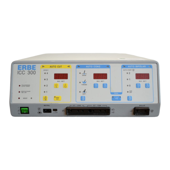
Page 23: Description Of The Controls
Description of the controls This symbol, in accordance with EN 60 601-1, is intended to indicate to the user that this unit must only be used on the patient if the user is acquainted with the operation and features of this unit. The figures set in cursive relate to the ICC illustration for this chapter, or to the function fields in the text. -
Page 24: Auto Cut Function Field
AUTO CUT function field All parameters can be set in this function field that are relevant to cutting: 2.1 Setting of the coagulation EFFECT when cutting Here the required cutting quality in regard to the coagulation effect on the cutting edges can be adjusted. -
Page 25: Auto Coag Function Field
AUTO COAG function field All parameters can be set in this function field that are relevant to coagulation: Selection of the coagulation mode By pressing this key, one of the following coagulation modes can be selected: Soft coagulation without Auto Stop Forced coagulation (Check the version. -
Page 26: Auto Bipolar Function Field
If you nevertheless wish to use the AUTO START function, please consult your local ERBE branch office. You will find the address on the last page of the Instruction Manual. Technical Service will activate the AUTO START function for you on request. -
Page 27: Connecting Socket For Neutral Electrodes
Activation, changeover switch for the blue pedal of a dual-pedal footswitch If the right signal 4.4.1 is illuminated in this key, the Auto Bipolar can be started via the blue pedal on a dual-pedal footswitch. Auto Bipolar can also be activated via the white pedal on a single-pedal footswitch or by Auto Start. -
Page 28: Connecting Socket For The Auto Bipolar Function Field
WARNING For simultaneous connection of two electrode handles to both monopolar connecting sockets 6 and 7, electrode handles (particularly if they look alike) must be laid down in such a way that there can be no mix-up. In case of doubt, a trial activation of the unit should be performed without contacting the patient with the active electrode. -
Page 29: Loudspeaker For Acoustic Signals
Volume of the acoustic signal The volume of the acoustic signals can be adjusted with this knob. This does not apply to warning signals which must always be sufficiently loud. WARNING An important purpose of this acoustic signal is to protect the patients and personnel from burns due to unintentional activation of the high-frequency generator (for more information, see Chapter 3.1.2, Unintentional activation of a high-frequency generator). -
Page 30: Description Of The Safety Features
4.3. Description of the safety features The ICC 300 is equipped with the following safety features: 4.3.1 OUTPUT ERROR = Automatic monitoring of unit-related output error 4.3.2 TIME LIMIT = Automatic monitoring of the time limit 4.3.3 NESSY = Neutral Electrode Safety System 4.3.4 Protection against operating error 4.3.1 Unit-related output error The ICC is equipped with automatic monitoring of the HF output... - Page 31 4.3.2 Time limit With normal use, a high-frequency generator is only activated briefly for performance of an incision or a coagulation by fingerswitch, pedal or AUTO START. This generally lasts only a few seconds. Through an error in the unit, in the accessories or in use, the high-frequency generator can be switched on unintentionally.
- Page 32 NESSY is a flexible Neutral Electrode Safety System that can be adapted optimally to the neutral electrodes selected by the user. For appropriate advice and adaptation to suit requirements, please contact your local Erbe office (see Chapter Addresses). 4-12...
- Page 33 WARNING For reasons of safety, a change to NESSY may only be made if it has been properly ensured that all users of this unit are informed in good time about this change. In addition, a change to NESSY must be properly documented. When using dual-surface neutral electrodes, NESSY also monitors the application direction of the contact surface relative to the direction of current flow.
- Page 34 Correct application The correct application must be observed not only for divided, but also for undivided neutral electrodes. WARNING Before the neutral electrode is applied to the patient’s body, a check must be made as to whether the green NESSY signal (LED) does not light when using a neutral electrode with two contact surfaces.
- Page 35 If a key on the electrode handle is shorted or bypassed at low resistance due to an error (e.g. by moisture in the electrode handle) or pressed while the power switch is switched on, this error is signaled acoustically and indicated by an Error Number after switching on the power switch.
- Page 36 4-16...
-
Page 37: Technical Data, Signals, Diagrams
TECHNICAL DATA, SIGNALS, DIAGRAMS Technical data Cutting, monopolar with automatic voltage control (AUTO CUT) HF voltage waveform unmodulated sinusoidal alternating voltage Crest factor C, at R = 500 ohms C = 1.4 for all setttings Rated frequency 330 kHz Maximum HF voltage at load resistance RL = ∞ 650 V Dynamic internal impedance in rated load range 0 ohm... - Page 38 Forced coagulation (FORCED COAG) HF voltage waveform pulse-modulated alternating voltage Crest factor C, at R =500 ohms C = 5 at 120 W , C = 11 at 5 W Rated of the HF voltage 1 MHz Peak value of the HF voltage Version 1 max.
- Page 39 Safety features Protection class according to EN 60 601-1 Type according to EN 60 601-1 Monitoring of single-surface neutral electrodes Automatic monitoring of the electrical connection between the neutral electrode and high-frequency surgical unit Monitoring of dual-surface neutral electrodes Automatic monitoring a) of the electrical connection between the neutral electrode and high-frequency surgical unit b) between the neutral electrode and patient...
-
Page 40: Visual And Acoustic Signals
Environmental conditions for operation of the unit Temperature +10°C to + 40°C Air humidity, relative 30% to 75%, noncondensing Visual and acoustic signals STATUS visual acoustic HF off • Power switch on •• •• •• Operating error on the front panel ••... -
Page 41: Diagrams
Diagrams AUTO CUT MODE, Effect 1, 2, 3, 4 Peak value of the HF output voltage U at no load, as a function of the power limitation P for EFFECT 1 to 4. - Page 42 HIGH CUT, Effect 1, 2, 3, 4 Peak value of the HF output voltage U at no load, as a function of the power limitation P for EFFECT 1 to 4.
- Page 43 SOFT COAGULATION AUTO BIPOLAR Peak value of the HF output voltage U at no load, as a function of the power limitation P...
- Page 44 FORCED COAGULATION Peak value of the HF output voltage U at no load, as a function of the power limitation P...
- Page 45 SPRAY COAGULATION Peak value of the HF output voltage U at no load, as a function of the power limitation P...
- Page 46 CUT MODE, Effect 1, 2, 3, 4 Power output as a function of load resistance for power limitation of 300 watts 5-10...
- Page 47 CUT MODE, Effect 1, 2, 3, 4 Power output as a function of load resistance for power limitation of 150 watts 5-11...
- Page 48 HIGH CUT, Effect 1, 2, 3, 4 Power output as a function of load resistance for power limitation of 300 watts 5-12...
- Page 49 HIGH CUT, Effect 1, 2, 3, 4 Power output as a function of load resistance for power limitation of 150 watts 5-13...
- Page 50 SOFT COAGULATION AUTO BIPOLAR Power output as a function of load resistance for 1) power limitation of 120 watts 2) power limitation of 60 watts 5-14...
- Page 51 FORCED COAGULATION Power output as a function of load resistance for 1) power limitation of 120 watts 2) power limitation of 60 watts 5-15...
- Page 52 SPRAY COAGULATION Power output as a function of load resistance for 1) power limitation of 120 watts 2) power limitation of 60 watts 5-16...
- Page 53 AUTO CUT MODE, Effect 1, 2, 3, 4 Power output as a function of the power limitation = 500 ohms 5-17...
- Page 54 HIGH CUT, Effect 1, 2, 3, 4 Power output as a function of the power limitation = 500 ohms 5-18...
- Page 55 SOFT COAGULATION AUTO BIPOLAR Power output as a function of the power limitation = 125 ohms 5-19...
- Page 56 FORCED COAGULATION Power output as a function of the power limitation = 350 ohms 5-20...
- Page 57 SPRAY COAGULATION Power output as a function of the power limitation = 500 ohms 5-21...
- Page 58 NESSY Dependence of the warning signals on contact resistance R between the two contact surfaces of ü a divided neutral electrode and the HF current I flowing through the entire surface of the neutral electrode: A = In this range, I is sufficiently small relative to R .
-
Page 59: Installation
INSTALLATION Spatial requirements High-frequency surgery units must only be operated in medically used rooms. The spatial requirements, in regard to electric installation, affect e.g. the grounded conductor system, the ground fault interrupt system, as well as measures for preventing electrostatic charges. The unit is used in rooms in which personnel can pick up electrostatic charges, for example in rooms with electrically nonconductive floors, thus touching the front panel of the units can lead to a brief illumination of light diodes or seven-segment displays due to discharge of an electrostatic... - Page 60 Protection against moisture ICC model series high-frequency surgical units are protected against the penetration of moisture in accordance with EN 60 601-2-2 . In spite of this, these units should not be set up in the vicinity of hoses or containers which contain liquids. Liquids should not be placed above or even on the unit.
- Page 61 6.11 Custom adaptation of the maximum time limit In consideration of the risk of thermal tissue damages due to unintentional switching on of an HF high-frequency generator, an unintentionally switched on HF generator should be switched off again as soon as possible automatically. Since the unit cannot automatically distinguish between intentional and unintentional switching on of an HF generator, the automatic switching off of an HF generator must not occur too quickly, because this would impair the operator during cutting and/or coagulation.
- Page 62 6.12 Versions of Forced Coagulation For Forced coagulation, the ICC generates brief voltage pulses with a high peak voltage. In this way, an effective hemostasis is achieved even with very small-surface electrodes, such as with TUR resection loops or laparoscopic retractors. However, these voltage pulses can cause more or less intensive disturbances in other electronic equipment, such as in video monitors.
- Page 63 6.13 Basic setting and custom programming of the basic setting If the unit is briefly (approx. 15 s) switched off and on again, the previous setting on the front panel appears and the unit can be used again immediately. If the unit is switched off for longer and switched on again, a freely programmable basic setting for the front panel appears, whereby all displays 2.3, 3.6 and 4.3 blink and the unit cannot be activated until this basic setting is confirmed by pressing any key.
- Page 64 The unit is equipped with a specific front panel basic setting. The specific basic setting is defined at the factory and cannot be changed by the user. This specific basic setting only appears if the basic setting freely programmable by the user is lost due to an error. For the ICC 300 unit, the following specific basic setting is defined at the factory: AUTO CUT EFFECT AUTO CUT MAX.WATT...
-
Page 65: Cleaning And Disinfection Of The Unit
CLEANING AND DISINFECTION OF THE UNIT Cleaning and disinfection of the unit The unit housing should only be cleaned and disinfected with nonflammable and nonexplosive agents. Make certain here that no moisture penetrates into the unit. We recommend a spray or wipe-down disinfection. However, the information from the disinfectant manufacturer absolutely must be observed here. -
Page 67: Performance Checks
PERFORMANCE CHECKS Before every application, the user should check the functional efficiency of the unit and the accessories. The ICC is equipped for this with various automatic performance checks that, each time the power switch is switched on, are performed briefly and then signal and display recognized errors. -
Page 68: Automatic Error Documentation
Automatic error documentation The ICC is a equipped with an automatic error recognition, error signaling and error documentation device. Errors are detected which are present or occur during switching on of the power switch, during the Self Check after switching on the power switch, during tests or during activation of the unit and/or of accessories connected to the unit. -
Page 69: Error List
Error list Error Error How to proceed No error No HF output voltage Notify the Technical Service HF output voltage too high Notify the Technical Service No HF output voltage Notify the Technical Service HF output voltage too high Notify the Technical Service Activation error Notify the Technical Service Activation error... - Page 70 When switching on the power switch, the Check whether there was an operating error or blue pedal on the dual-pedal footswitch whether the blue pedal of the dual-pedal footswitch or or the white pedal on the single-pedal the white pedal of the single-pedal footswitch is footswitch was already pressed defective When switching on the power switch,...
-
Page 71: Safety Checks
SAFETY CHECKS To prevent a reduction in safety for the unit due to age, wear etc., § 6 of the regulation concerning the installation, operation and use of active medical products (BetreibVaMP) prescribes regular safety checks. The operator must have the safety checks which have been established for this unit properly performed to the prescribed extent. - Page 73 MAINTENANCE, CARE AND DISPOSAL OF THE UNIT 10.1 Maintenance of the unit including reusable accessories Maintenance of the unit including the reusable accessories includes preventive and corrective measures for servicing. Therefore established, regularly performed safety checks (see Chapter 9) represent preventive measures, while changes and repairs can be summarized under the category of corrective maintenance.
- Page 74 10-2...
-
Page 75: Guarantee
Other claims, particularly claims of damage compensation, are excluded. Repair must only be performed by ERBE, one of our representatives, or by an authorized retailer. The claim of guarantee becomes void if improper changes or repairs were made. - Page 76 11-2...
Need help?
Do you have a question about the ERBOTOM ICC 300 and is the answer not in the manual?
Questions and answers