
Related Manuals for Erbe APC 2


Summary of Contents for Erbe APC 2
- Page 1 SERVICE MANUAL APC 2 V 1.2.x V 1.3.x V 1.4.x PLASMASURGERY 80116-276_V24169 2022-01...
- Page 3 SERVICE MANUAL APC 2...
- Page 4 (by photocopying, microfilming or other methods) or processed, duplicated or dissem- inated by the use of electronic systems without the written consent of Erbe Elektromedizin GmbH. The information contained in this manual may be amended or supplemented without prior notice and represents no obli- gation on the part of Erbe Elektromedizin GmbH.
-
Page 5: Table Of Contents
Block diagram APC 2........ - Page 6 Instrument recognition multifunction sockets ......48 Fingerswitch activation APC 2 + VIO D.......49 Fingerswitch activation APC 2 + VIO S .
-
Page 7: Safety Information
Protection from the risk of electric shock WARNING! Disconnect the APC 2 from the electrosurgical unit (interconnection and ECB cable) before replacing parts inside the unit or cleaning the unit. WARNING! Do not touch any unprotected wires or conductive surfaces while the unit is opened and under voltage. -
Page 8: Handling Of Argon Pressure Cylinders
Liability and warranty ATTENTION! Adjustments, tests, modifications, maintenance and repair work may only be performed by Erbe or persons trained by Erbe. If the work is not performed by trained persons, Erbe accepts no liability and warranty rights become void. -
Page 9: Modifications
Modifications The changes relevant to APC 2 vary depending on which VIO electrosurgi- cal unit (VIO D or VIO S) the APC 2 is connected to. They are therefore only described in the service manuals for the VIO electrosurgical units. - Page 10 2 • Modifications / 62...
-
Page 11: Controls
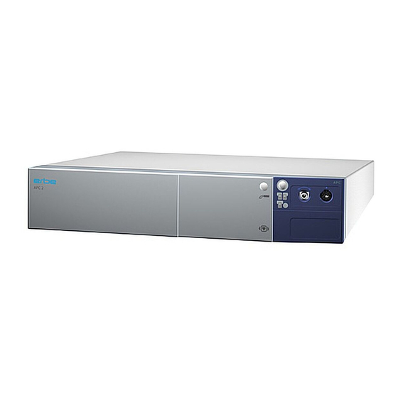
User Manual for the unit(s), knowledge of which is assumed for servicing work, provides detailed information about how to use the unit(s). Controls at the front Version 1.2.x APC 2 APC 2 Fig. 3-1 Purge button Focus button FiAPC socket Pilot lamp „No ECB data link“... -
Page 12: From Version 1.3.X
As from V 1.3.x the APC module can take two sockets. One of these sockets must be a APC socket. The second socket can be either a HF socket or, as from V 1.4.x a second APC socket. APC 2 APC 2 Fig. 3-2... -
Page 13: Controls At The Rear
3 • Controls Controls at the rear Fig. 3-3 Purge pin Argongas connector Pressure sensor terminal ECB sockets (Erbe Communication Bus) Potential equalization terminal / 62... - Page 14 3 • Controls / 62...
-
Page 15: Technical Data
4 • Technical Data CHAPTER 4 Technical Data Connections Low voltage via VIO electrosurgical unit via VIO electrosurgical unit Terminal for potential equalisation Gas specification Type of gas Argon Argon minimum purity Argon 4.8 (99.998% purity) or higher, e.g. argon 5.0. Density (relative;... - Page 16 Gas-specific unit data Residual volume display VIO display Residual pressure display Pressure gauge The APC 2 switches off when the input pressure is < 3 x 10 < 3 bar < 43.5 psi Dimensions and weight Width x height x depth...
-
Page 17: Circuit Descriptions
5 • Circuit Descriptions CHAPTER 5 Circuit Descriptions / 62... -
Page 18: Block Diagram Apc 2
5 • Circuit Descriptions Block diagram APC 2 Fig. 5-1 / 62... -
Page 19: Description Of The Various Assemblies
If a button is pressed on the APC 2, the "APC controller" signals this to the control panel via the ECB. In return it is informed which LED indicators must be switched on. -
Page 20: Iif (Instrument Interface)
IIF (Instrument Interface) The instrument interface assembly may be found up to four times in the VIO system: twice in the electrosurgical unit and twice in the APC 2 unit and VEM 2 unit respectively. The IIF is used to provide the system with the key instrument information... -
Page 21: Setup And Service Settings
VIO electrosurgical unit to which the APC 2 is connected. The setup and service settings vary depending on which VIO electrosurgi- cal unit (VIO D or VIO S) the APC 2 is connected to. They are therefore only described in the service manuals for the VIO electrosurgical units. - Page 22 6 • Setup and Service settings / 62...
-
Page 23: Test Programs
CHAPTER 7 Test programs The test programs relevant to the APC 2 are called up and used from the VIO electrosurgical unit to which the APC 2 is connected. The test programs vary depending on which VIO electrosurgical unit (VIO D or VIO S) the APC 2 is connected to. - Page 24 7 • Test programs / 62...
-
Page 25: Adjustment
Personnel requirements ATTENTION! Adjustments, technical tests, modifications, maintenance and repair work may only be performed by Erbe or persons trained by Erbe. If the work is not performed by trained persons, Erbe accepts no liability and warranty rights become void. -
Page 26: Test Equipment
8 • Adjustment Test equipment IMPORTANT! The following list contains the testing and measuring equipment rec- ommended by Erbe for servicing. Where Erbe article numbers are spec- ified, only original Erbe testing and measuring equipment should be used. Erbe Art. No. -
Page 27: Test Setup
Fig. 8-1 • The test setup is designed as shown in the illustration above. In this case a unit combination comprised of APC 2 + VIO D serves as an example. • On the PC the "VIO APC Adjustment Tool" software is installed. -
Page 28: Test Procedure
The voltage input of the APC 2 is not protected against reverse polarity. Connecting up the wrong way round will damage the unit. 1. Connect APC 2 to 24 V power supply. For this purpose connect the VIO HF surgical unit to the APC 2. -
Page 29: Troubleshooting
9 • Troubleshooting CHAPTER 9 Troubleshooting ERROR list The error messages relevant to the APC 2 are displayed on the VIO elec- trosurgical unit to which the APC 2 is connected. They are accompanied by the abbreviation "A". / 62... -
Page 30: A/E-Errors
9 • Troubleshooting Status of the ERROR list: 07.13 A/E-Errors Recognizing module: A = APC 2, E = Extension module VEM 2 Recog- Error Additional informa- Description Action nizing code tion module Timeout of activation signal. ECB communication inter- rupted. Check or trouble- shoot ECB connecting cables. - Page 31 9 • Troubleshooting Recognizing module: A = APC 2, E = Extension module VEM 2 Recog- Error Additional informa- Description Action nizing code tion module CAN error. Reprogram unit (modules) Load compatible software. Underpressure at selected Check the gas supply (tank, gas input.
- Page 32 9 • Troubleshooting Recognizing module: A = APC 2, E = Extension module VEM 2 Recog- Error Additional informa- Description Action nizing code tion module The APC 2/VEM 2 first Information, no fault condi- receives a one-second signal tion. from the IES 2 and then from Change the activation the VIO.
- Page 33 9 • Troubleshooting Recognizing module: A = APC 2, E = Extension module VEM 2 Recog- Error Additional informa- Description Action nizing code tion module Internal state incorrect. Information, no fault condi- tion. Protocol violation CAN. Reprogram unit (modules) Load compatible software.
- Page 34 9 • Troubleshooting / 62...
-
Page 35: Maintenance And Servicing
ATTENTION! Adjustments, tests, modifications, maintenance and repair work may only be performed by Erbe or persons trained by Erbe. If the work is not performed by trained persons, Erbe accepts no liability and warranty rights become void. It is recommended that the technical safety check also be performed by Erbe or persons trained by Erbe. -
Page 36: Testing And Measuring Equipment
Testing and measuring equipment IMPORTANT! The following lists contain the testing and measuring equipment rec- ommended by Erbe for servicing. Where Erbe article numbers are spec- ified, only original Erbe testing and measuring equipment should be used. For APC sockets, and FiAPC sockets on the APC 2 Erbe Art. -
Page 37: For Hf Sockets On The Apc 2
20189-303 Dual-pedal footswitch with ReMode 20100-039 NF cable – leakage current 20100-105 VIO test box pressure simulator (APC 2/Endo pressure simulator) – VIO APC Adjustment Tool (software, on request) 20100-164 Service Support Hardware USB (only for internal use by Erbe) For HF sockets on the APC 2 Erbe Art. -
Page 38: Technical Safety Check - Step By Step
VIO HF surgical unit and the actual test specimen (APC 2) which is tested because the test specimen does not have it own built-in power supply unit. -
Page 39: User Manual And Visual Inspections
10 • Maintenance and servicing User manual and visual inspections • Test specimen and accessories (where enclosed) undamaged exter- nally. • Pressure regulator externally intact with no leaks. • User manual present. • All labels on the test specimen (conformity declaration mark, rating plate, and all wording) present and readily legible. -
Page 40: Pressures
10 • Maintenance and servicing Pressures Testing and measuring equipment IMPORTANT! For this test only Erbe pressure reducers may be used. For article num- bers see chapter "Testing and measuring equipment". Erbe Art. No. Description 20100-108 Manometer 20134-XXX Pressure regulator... - Page 41 "A-40". Bottle pressure detection This test is performed in different ways depending on whether the APC 2 is connected to a VIO D or a VIO S electrosurgical unit. APC 2 + VIO D...
- Page 42 2. Press Purge button. The test specimen must display the warning "A- 90". Bottle pressure detection This test is performed in different ways depending on whether the APC 2 is connected to a VIO D or a VIO S electrosurgical unit. APC 2 + VIO S Test setup •...
-
Page 43: No Leaks At 5 Bar Input Pressure
10 • Maintenance and servicing No leaks at 5 bar input pressure Testing and measuring equipment IMPORTANT! For this test only Erbe pressure reducers may be used. For article num- bers see chapter "Testing and measuring equipment". Erbe Art. No. Description... -
Page 44: Purge Function
5 minutes. Purge function Testing and measuring equipment IMPORTANT! For this test only Erbe pressure reducers may be used. For article num- bers see chapter "Testing and measuring equipment". Erbe Art. No. Description... -
Page 45: Gas Flow Measurement
1. Depending on the bottle connection. 2. The APC Purge Duration is set at setup level 2 in the case of the APC 2 + VIO D combination and in service level for the APC 2 + VIO S combination. - Page 46 10 • Maintenance and servicing Test setup ITP Omega 30100-528 Argon Fig. 10-1 • The test specimen is connected to the power supply via a VIO HF surgi- cal unit. A VIO D unit serves as an example in this case. •...
-
Page 47: Instrument Recognition Apc Socket
10 • Maintenance and servicing Instrument recognition APC socket Testing and measuring equipment Erbe Art. No. Description 20100-037 APC measuring cable 20132-043 APC handle 20100-021 APC test box Instrument recognition via Test setup resistance • The test specimen is connected to the power supply via a VIO electro- surgical unit. -
Page 48: Instrument Recognition Fiapc Socket
2. Remove test adapter. The test specimen must recognize and indicate removal of the adapter. Instrument recognition multifunction sockets This test can only be performed with the following combination: APC 2 + VIO 300 D. Testing and measuring equipment Erbe Art. No. -
Page 49: Fingerswitch Activation Apc 2 + Vio D
10 • Maintenance and servicing Fingerswitch activation APC 2 + VIO D This test is performed in different ways depending on whether the APC 2 is connected to a VIO D or a VIO S electrosurgical unit. Testing and measuring equipment Erbe Art. - Page 50 Test setup (Activation FORCED APC) IMPORTANT! For this test only Erbe pressure reducers may be used. For article num- bers see chapter "Testing and measuring equipment". • The test specimen is connected to the power supply via a VIO D HF surgical unit.
-
Page 51: Fingerswitch Activation Apc 2 + Vio S
The argon must ignite. Fingerswitch activation APC 2 + VIO S This test is performed in different ways depending on whether the APC 2 is connected to a VIO D or a VIO S electrosurgical unit. Testing and measuring equipment Erbe Art. - Page 52 (Activation FORCED APC) IMPORTANT! For this test only Erbe pressure reducers may be used. For article num- bers see chapter "Testing and measuring equipment". • The test specimen is connected to the power supply via a VIO S HF sur- gical unit.
-
Page 53: Hf Socket Performance Test
VIO electrosurgical unit. Monopolar / MF socket 1. With APC 2 + VIO D: Perform tests as described in the chapter "Fin- gerswitch activation", Service Manual VIO D. 2. With APC 2 + VIO S: Perform tests as described in the chapter "Finger- switch activation", Service Manual VIO S. - Page 54 10 • Maintenance and servicing / 62...
-
Page 55: Spare Parts
11 • Spare parts CHAPTER 11 Spare parts 40134-030 (1) 55021-000 (1) 30134-002 (1) 40134-000 (1) 30134-803 (1) Fig. 11-1 / 62... - Page 56 11 • Spare parts Fig. 11-2 / 62...
- Page 57 11 • Spare parts Fig. 11-3 / 62...
- Page 58 11 • Spare parts 30134-801 (1) 30134-802 (1) 40134-040 (1) Fig. 11-4 / 62...
- Page 59 11 • Spare parts Fig. 11-5 / 62...
-
Page 60: Circuit Boards
11 • Spare parts Circuit Boards Fig. 11-6 / 62... -
Page 61: Socket Modules
As from V 1.3.x the APC module can take two sockets. One of these sockets must be a APC socket. The second socket can be either a HF socket or, as from V 1.4.x a second APC socket. APC sockets Erbe Art. No. 20134-651 Socket module FiAPC Fig. 11-7 Bipolar sockets Erbe Art. -
Page 62: Multifunction Sockets
11 • Spare parts Erbe Art. No. 20140-623 Socket module MO 3Pin, 9/5 Fig. 11-11 Multifunction sockets Erbe Art. No. 20140-630 Socket module MF 0 Fig. 11-12 Erbe Art. No. 20140-633 Socket module MF-2 Fig. 11-13 / 62...
Need help?
Do you have a question about the APC 2 and is the answer not in the manual?
Questions and answers