
Subscribe to Our Youtube Channel
Related Manuals for AXIOMTEK ITC150WM


Summary of Contents for AXIOMTEK ITC150WM
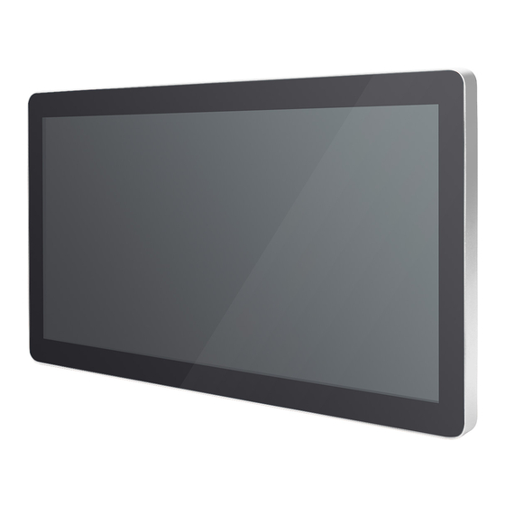
- Page 1 ITC150WM 15.6" FHD TFT-LCD Slim Bezel Modular Panel PC Powered by Intel® Smart Display Module (SDM) User’s Manual...
- Page 2 Disclaimers This manual has been carefully checked and believed to contain accurate information. Axiomtek Co., Ltd. assumes no responsibility for any infringements of patents or rights of any third party, and any liability arising from such use. Axiomtek does not warrant or assume any legal liability or responsibility for the accuracy, completeness or usefulness of any information in this document.
-
Page 3: Safety Precautions
Most electronic components are sensitive to static electrical charge. Disconnect all power cords from the ITC150WM Series before making any installation. Be sure both the system and the external devices are turned OFF. Sudden surge of power could ruin sensitive components. Make sure the ITC150WM series is properly grounded. -
Page 4: Table Of Contents
Table of Contents Disclaimers ..................... ii Safety Precautions ..................iii Section 1 Introduction ..........1 General Description ................1 ITC150WM Specifications ..............2 Smart Display Module –( SDM 300S module) ..........2 1.2.1 1.2.2 I/O System ....................2 1.2.3 System Specifications ................. 3 Dimensions .................. - Page 5 Security Menu ..................36 Boot Menu ..................37 Save & Exit Menu ................38 Section 4 Drivers Installation ......41 System ....................41 4.1.1 Windows 10 ....................41 Touch Screen ..................41...
- Page 6 This page is intentionally left blank.
-
Page 7: Introduction
Package List General Description ITC150WM is Modular Panel PC ,equipped with a 15.6” TFT LCD display and low power consumption processor, Intel® SDM CPU card (processor Celeron® Processor N3350 with 2M cache, up to 2.4 GHz) or Intel® Pentium® Processor N4200 (with 2M Cache, up to 2.5 GHz). It is compatible with Windows 10 and supports on board eMMC for storage and one M.2 card... -
Page 8: Itc150Wm Specifications
ITC150WM User’s Manual ITC150WM Specifications 1.2.1 Smart Display Module –( SDM 300S module) CPU CARD (SDM) Intel® Celeron® Dual Core Processor N3350 (2M Cache, up to 2.4 GHz) onboard. Intel® Pentium® Quad Core Processor N4200 (2M Cache, up to 2.5 GHz) onboard. -
Page 9: System Specifications
ITC150WM User’s Manual 1.2.3 System Specifications 15.6" FHD TFT-LCD Slim Bezel with LED backlight Projected capacitive multi-touch 10 point Fanless heat dissipation design Disk housing By SDM Module Net weight 3.15 kg ... -
Page 10: Dimensions
ITC150WM User’s Manual Dimensions ITC150W M outlines and dimensions ITC150 + SDM300S Introduction... - Page 11 ITC150WM User’s Manual ITC150 + SDM500L Introduction...
-
Page 12: I/O Outlets
ITC150WM User’s Manual I/O Outlets Please refer to Figures 1-1 and 1-2 for controls and I/O locations at the bottom of the ITC-150W M. Figure 1-1 Front view of the ITC-150WM Figure 1-2 Left side view and button view of the ITC-150WM... -
Page 13: Packing List
Accessories package of the ITC-150WM should contain the following items: ITC150WM System x 1 DC cable User manual x 1 Adapter x 1 (Optional) Please contact an Axiomtek distributor immediately if any item is missing. Introduction... - Page 14 ITC150WM User’s Manual This page is intentionally left blank. Introduction...
-
Page 15: Hardware And Installation
ITC150WM User’s Manual Section 2 Hardware and Installation The ITC150WM provides rich I/O ports and flexible expansions for users to meet different demands. This section is describing hardware installation, including the following subsections: Jumper and Connector Settings Port Definitions ... -
Page 16: Jumper Settings
ITC150WM User’s Manual 2.1.1 Jumper Settings By making proper jumper settings, users can configure the board SDB101 to suit the needs of their applications. Jumper is a small component consisting of jumper clip and jumper pins. Install jumper clip on 2 jumper pins to close. -
Page 17: Connector Settings
ITC150WM User’s Manual 2.1.2 Connector Settings The connectors on the Carrier board allow the SDM module to connect with other parts of the system. Ensure that all connectors are in place and firmly attached. Table 2-2 lists the function of each connector on the board SDB101. - Page 18 ITC150WM User’s Manual USB2.0 Connector(USB2 & USB1) Signal USB_VCC (+5V level ) USB _D- USB _D+ USB3.0 Connector(USB3) Signal USB_VCC (+5V level standby power) USB #1_D- USB #1_D+ USB1_SSRXN USB1_SSRXP USB1_SSTXN USB1_SSTXP HDMI Connector (HDMI1) Signal Signal HDMI IN_DATA2+ HDMI IN_DATA2-...
- Page 19 ITC150WM User’s Manual Internal USB2.0 (USB4~6) PHD 2.0mm 1192-700-05RMR Signal VCC (+5V level ) USBn USBp I2C Connector(I2C-1~2) PHD 2.0mm 1192-700-05RMR Signal 3.3V Programing connector (prog1) Dupont 2.0mm Signal eDP (EDP1) Pin Signal Pin Signal BKLTCTL N.C. BKLTEN eDP_BIST +DVCCM1...
- Page 20 ITC150WM User’s Manual Internal LVDS Connector (LVDS1) This board has a 40-pin connector (SCN5) for LVDS LCD interface. It is strongly recommended to use the matching JST SHDR-40VS-B 40-pin connector for LVDS interface. Pin 1~6 VCCM can be set to +3.3V level or +5V level by JP2 (see section 2.2).
- Page 21 ITC150WM User’s Manual Inverter Connector (INV1) The CN12 is a DF13-8S-1.25V 8-pin connector for inverter. We strongly recommend you to use the matching DF13-8S-1.25C connector to avoid malfunction. Signal VBL1 (+12V level) VBL1 (+12V level) VBL2 (+5V level) VBL_ENABLE VBL Brightness Control...
-
Page 22: Mountings - Vesa
Mountings – VESA There are several ways to mount the ITC150: Wall, desktop, VESA and panel mounting. 2.2.1 Panel-Mounting (optional) The ITC150WM is designed for panel mount application. Step1 Sticks four sealing pads on the edges of the chassis. Step2 Assemble the panel kit onto the chassis and fasten the five screws. -
Page 23: Assembling The Wall Mount Bracket
ITC150WM User’s Manual 2.2.2 Assembling the Wall Mount Bracket The ITC150WM provides a wall mount bracket (VESA 100 x 100 mm). Screw four screws to fix the kit in the back chassis. Step 1 Find out the screw holes to assemble the wall mount bracket on the back side of the chassis with four screws. -
Page 24: Assembling The Stand
ITC150WM User’s Manual 2.2.3 Assembling the stand The ITC150WM supports VESA mount: 100 x 100 mm. Screw four screws to fix the stand kit in the back chassis. Find out the screw holes to assemble the stand kit with four screws, as shown by the red marks in the below picture. -
Page 25: Storage Installation
NOTE Please refer SDM module specification 2.3.2 MicroSD Card Installation The ITC150WM provides one MicroSD card slot for users to install a MicroSD card. Step 1 Push the MicroSD card into the slot until it has been locked firmly. Step 2 Pull the microSD memory card out of the slot mark area. -
Page 26: Wireless Card Installation
ITC150WM User’s Manual M.2 Wireless Card Installation The ITC150WM supports one M.2 slot for wireless module (option) installation. Please find instructions as follows: Step 1 The SDM can be easily removed by loosening the thumbscrews and sliding it out. Step 2 Insert the M.2 wireless card into the M.2 slot as shown in the red mark area. -
Page 27: Ami Bios Setup Utility
ITC150WM User’s Manual Section 3 AMI BIOS Setup Utility This section provides users with detailed descriptions about how to set up basic system configuration through the AMI BIOS setup utility. Navigation Keys The BIOS setup/utility uses a key-based navigation system called hot keys. Most of the BIOS setup utility hot keys can be used at any time during the setup navigation process. -
Page 28: Main Menu
ITC150WM User’s Manual Main Menu When you first enter the setup utility, you will enter the Main setup screen. You can always return to the Main setup screen by selecting the Main tab. System Time/Date can be set up as described below. -
Page 29: Advanced Menu
ITC150WM User’s Manual Advanced Menu Figure 3-2 Advanced menu The Advanced menu allows users to set configurations of the CPU and other system devices. Select any item on the left to go to the sub-menus (as shown in Figure 3-2). -
Page 30: Trusted Configuration
ITC150WM User’s Manual 3.3.1 Trusted Configuration Figure 3-4 Trusted Configuration page Security Device support This option is used to enable or disable TPM function AMI BIOS Setup Utility... -
Page 31: Acpi Settings
ITC150WM User’s Manual 3.3.2 ACPI Settings Figure 3-4 shows a screen reflecting the ‘ACPI Settings’ of the hardware in real time. This screen is used to select options of the ACPI Configuration, and then change the value of the selected option. A description of the selected item appears on the right side of the screen. -
Page 32: Nct5104D Super Io Configuration
ITC150WM User’s Manual 3.3.3 NCT5104D Super IO configuration You can use this screen to select options for the Serial Port Configuration, and change the value of the selected option. A description of the selected item appears on the right side of the screen. -
Page 33: Cpu Configuration
ITC150WM User’s Manual 3.3.4 CPU Configuration This screen shows the CPU Configuration, and you can change the value of the selected option. Figure 3-6 Entering ‘CPU Configuration’ Socket 0 CPU Information This screen shows the CPU information. AMI BIOS Setup Utility... - Page 34 ITC150WM User’s Manual CPU Power Management Configuration EIST Enable or disable Intel SpeedStep mode. The default setting is Enabled. Turbo Mode Enable or disable turbo mode. The default setting is Disabled. C-states Enable or disable C states. The default setting is Enabled.
-
Page 35: Network Stack Configuration
ITC150WM User’s Manual 3.3.5 Network Stack Configuration Figure 3-7 Entering “Network Stack Configuration” Network Stack Enable or disable UEFI Network stack. The default setting is Disabled. AMI BIOS Setup Utility... -
Page 36: Csm (Compatibility Support Module) Configuration
ITC150WM User’s Manual 3.3.6 CSM (Compatibility Support Module) Configuration Figure 3-8 Entering ‘CSM (Compatibility Support Module) Configuration CSM Support Enable or disable CSM support. The default setting is Enabled. Boot optional filter Controls the priority of Legacy and UEFI ROMs. - Page 37 ITC150WM User’s Manual 3.3.7 USB Configuration Figure 3-9 Entering “USB Configuration” USB Devices Display all detected USB devices. Legacy USB Support Enable or disable legacy USB support. USB Mass Storage Driver Support Enable or disable USB mass storage driver support.
-
Page 38: Chipset Menu
ITC150WM User’s Manual Chipset Menu The Chipset menu gives memory information about South Bridge (see Figure 3-9). Figure 3-9 South Cluster Configuration AMI BIOS Setup Utility... -
Page 39: South Cluster Configuration
ITC150WM User’s Manual 3.4.1 South Cluster Configuration This screen shows South Cluster configuration. For items marked with , please press <Enter> for more options PCI Express configuration information is shown in Figure 3-10 Figure 3-10 PCI Express configuration’ AMI BIOS Setup Utility... - Page 40 ITC150WM User’s Manual PCI Express Configuration This screen shows PCI Express configuration. For items marked with , please press <Enter> for more options PCIE Root Port5 (NGFF1) Control PCIE root port5. The default setting is Enable. ASPM Control PCI Express active state power management settings.
- Page 41 ITC150WM User’s Manual SCC eMMC Support (D28:F0) Enable or disable eMMC support. The default setting is Enable. AMI BIOS Setup Utility...
-
Page 42: Security Menu
ITC150WM User’s Manual Security Menu You may set the administrator/user password for the system. Figure 3-12 Security Menu AMI BIOS Setup Utility... -
Page 43: Boot Menu
ITC150WM User’s Manual Boot Menu The Boot menu allows users to change boot options of the system. Users can highlight any of the items on the left frame of the screen to go to any particular sub menus (as shown in Figure 3-13). -
Page 44: Save & Exit Menu
ITC150WM User’s Manual Save & Exit Menu Figure 3-14 Save & Exit Menu Save Changes and Exit When users have completed the system configuration changes, select this option to leave Setup and return to Main Menu. Select Save Changes and Exit from the Save & Exit menu and press <Enter>. - Page 45 ITC150WM User’s Manual Save Changes After completing the system configuration changes, select this option to save changes. Select Save Changes from the Save & Exit menu and press <Enter>. Select Yes to save changes. Discard Changes Select this option to quit Setup without making any permanent changes to the system configurations.
- Page 46 ITC150WM User’s Manual This page is intentionally left blank. AMI BIOS Setup Utility...
-
Page 47: Drivers Installation
ITC150WM User’s Manual Section 4 Drivers Installation System The ITC150WM supports Windows 10 pro and Windows 10 IoT Enterprise. To facilitate the installation of the system driver, please carefully read the instructions in this chapter before installation. 4.1.1 Windows 10 Insert the driver CD and select the folders from step 1 to step 5.
Need help?
Do you have a question about the ITC150WM and is the answer not in the manual?
Questions and answers