Table of Contents

Related Manuals for LaserLine GL3000PM


Summary of Contents for LaserLine GL3000PM
- Page 1 LaserLine Manufacturing, Inc. GL3000PM OWNER’S MANUAL Guidance Alignment Laser 1810 SE First Street, Suite H, Redmond, OR 97756 Phone 541 548 0882 • Fax 541 548 0892 • Email laserline@laserline.net Website www.LaserLineMfg.com REV. 10.2.20...
-
Page 2: Table Of Contents
Section I Operator’s Manual System Overview: What it Does & How it Works Operator Controls Maintenance, Service & Installation Suggestions Using the GL3000PM Laser GL3000PM Specifications GL3000PM Series Warranty Section II Laser Safety Laser Safety Considerations Laser Safety Controls &... -
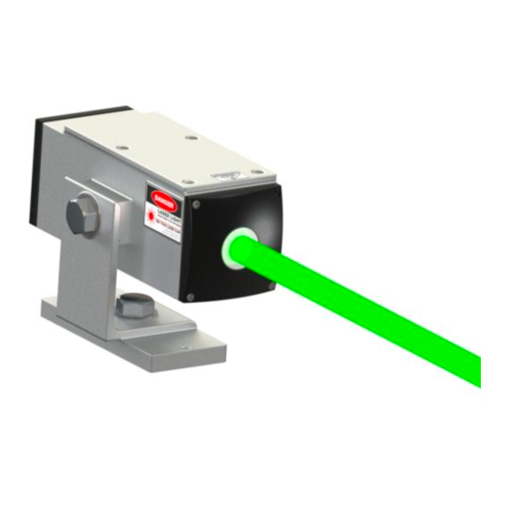
Page 3: System Overview: What It Does & How It Works
THE SYSTEM THE PRODUCT • Main Housing — Weatherproof, containing optic The GL3000PM Laser uses an ultra high visibility green plate mounting platform, micro processor electronics, laser to establish visual line control for your paint strip- laser, laser mounting assembly, laser driver board, ing machine, gun carriage package, asphalt distributor, automatic cooling and heating system. -
Page 4: Operator Controls
OPERATOR CONTROLS Images for Control Panel and Laser Assy page CONTROL BOX Main Power Switch Images for Control Panel and Laser Assy page Power Indicator Light Main System Laser Mode Switch 1st depression = On Steady 2nd depression = Blink Mode 3rd depression = Off Laser Status Light •... -
Page 5: Maintenance, Service & Installation Suggestions
MAINTENANCE INSTALLATION SUGGESTIONS The only maintenance that may be required is: 1. Mount the GL3000PM Laser on the vehicle at least 5 feet off the ground. Most Operators prefer to mount • Periodically clean the Exit Window of the GL3000PM. -
Page 6: Using The Gl3000Pm Laser
USING THE GL3000PM LASER USING THE GL3000PM 1. Turn on the Main Power Switch about10-15 minutes prior to use. This puts the laser module in the “preheat” mode to bring it up to operating temperature. The laser mode power status light will slow-blink while it’s warm- ing up. -
Page 7: Gl3000Pm Specifications
LaserLine Mfg., Inc. liability under this warranty is limited to repairing or replacing any product returned to an authorized service center for that purpose. Any evidence of attempts to repair this unit by other than factory authorized personnel automatically voids the warranty. -
Page 8: Section Ii Laser Safety
LASER OPERATOR TRAINING AND QUALIFICATION CARD LASER SAFETY CONSIDERATIONS reverse side of this card and is qualified to operate Laserline Post at least one LaserLine laser warning placard at each laser reverse side of this card and is qualified to operate Laserline Post at least one LaserLine laser warning placard at each laser Manufacturing, Inc. -
Page 9: Laser Safety
LASER SAFETY SAFETY CONSIDERATIONS: The GL3000 Series Laser is a Class IIIa Laser Product generating less than 5 milliwatts of Laser Light. Class • When installing the GL3000 Laser, do not mount IIIa Lasers are used every day in construction and the laser inside the cab and shoot the laser beam alignment applications. -
Page 10: Controls & Emissions
Controls & Emissions CONTROLS & EMISSIONS Controls: 1). System Power Switch with corresponding LED (RED) rols & Emissions 2). Laser Mode Switch CONTROLS with corresponding Indicator (Green) Controls: 1st depression = On Steady mode System Power Switch 1). System Power Switch 2nd depression = Blink Mode with Red LED with corresponding LED (RED) -
Page 11: Gl3000Pm Product Labeling
GL3000PM PRODUCT LABELING Note: Maintain these labels in there proper locations. Certification Label Certification Label Aperture Label Aperture Label dentification Label Identification Label Warning Logotype ocated Underside Warning Logotype Label Located Underside at the Rear at the Rear...
Need help?
Do you have a question about the GL3000PM and is the answer not in the manual?
Questions and answers