
Related Manuals for Creative Play QUARTER MASTER


Summary of Contents for Creative Play QUARTER MASTER
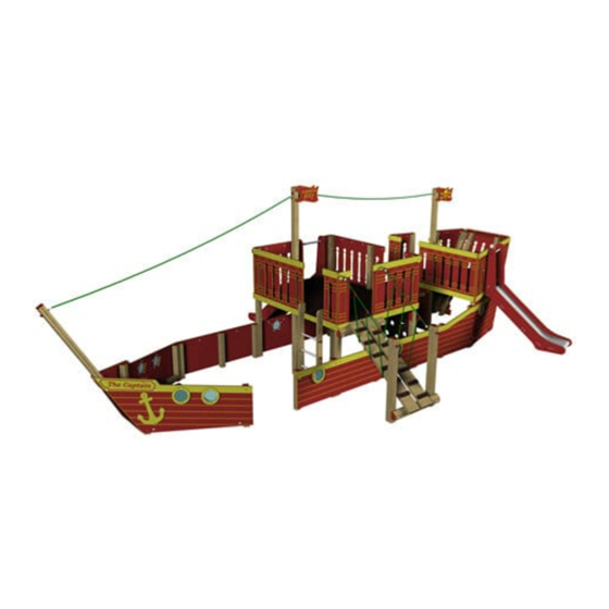
- Page 1 QUARTER MASTER Installation Instructions VOY123 - THE CAPTAIN VOY121 - FIRST MATE REF: VOY122 - QUARTER MASTER pg 1 of 48...
-
Page 2: Parts Required
PARTS required PARTS required BOW Timbers CODE TYPE SIZE VOY121-B1 90x90 2700 VOY121-B VOY121-B3 (ASSEMBLY) ASSEMBLY BOW Pre-assembled parts STARBOARD FRONT (BOW PANEL) (BOW PANEL) PORTSIDE STAIRS (BOW PANEL) (BOW) REF: VOY122 - QUARTER MASTER pg 2 of 48... - Page 3 (FM180 WOOD SCREWS) (M12 x 130* CUP SQUARE BOLTS) (COVERED END) (M12 NYLOCS) ENTRY ‘OPEN FRONT’ Pre-assembled parts PORTSIDE STARBOARD (ENTRY PANEL) (ENTRY PANEL) ENTRY ‘OPEN FRONT’ fixings (FM80 WOOD SCREWS) REF: VOY122 - QUARTER MASTER pg 3 of 48...
- Page 4 MAIN DECK Timbers VOY122-M VOY122-M VOY122-M VOY122-M VOY122-M VOY122-M VOY122-M VOY122-M VOY122-M VOY122-M VOY122-M LADDER ASSEMBLY GANGPLANK ASSEMBLY MAIN DECK Pre-assembled parts PANELf PANELc PANELa PANELb PANELc/f (MAIN DECK) (MAIN DECK) (MAIN DECK) REF: VOY122 - QUARTER MASTER pg 4 of 48...
- Page 5 PARTS required MAIN DECK Pre-assembled parts PANELd PANELe (MAIN DECK) (MAIN DECK) 1.0m SLIDE GANGPLANK (MAIN DECK) (MAIN DECK) LADDER GANGPLANK (MAIN DECK) (MAIN DECK NET) REF: VOY122 - QUARTER MASTER pg 5 of 48...
- Page 6 (M12 x 200* CUP SQUARE BOLTS) (FM80 WOOD SCREWS) (M12 x 230* CUP SQUARE BOLTS) (FM120 WOOD SCREWS) (M12 x 290* CUP SQUARE BOLTS) (Polyfix halves) INC POLYFIX HALF SCREWS (M12 NYLOCS) (M10 NYLOCS) (COVERED END) REF: VOY122 - QUARTER MASTER pg 6 of 48...
- Page 7 VOY121-S VOY121-S VOY121-S VOY121-S S10b VOY121-S VOY121-S PANELh ASSEMBLY PANELh ASSEMBLY PANELc ASSEMBLY PANELc ASSEMBLY NOT REQUIRED VOY121-S PANELc ASSEMBLY VOY121-S S10a STERN Pre-assembled parts PANELb PANELa PANELc (STERN) (STERN) (STERN) REF: VOY122 - QUARTER MASTER pg 7 of 48...
- Page 8 PARTS required STERN Pre-assembled parts PANELg PANELf PANELh (STERN) (STERN) (STERN) STERN PANELi REAR STERN PANELj REAR PANELi / PANELj 1.0m SLIDE (STERN) (STERN) Starboard Portside SHIPS WHEEL FLAG (STERN) REF: VOY122 - QUARTER MASTER pg 8 of 48...
- Page 9 END COVER (STERN) (STERN) STERN Fixings (FM80 WOOD SCREWS) (M12 x 120* CUP SQUARE BOLTS) (M12 x 130* CUP SQUARE BOLTS) (M12 x 200* CUP SQUARE BOLTS) (COVERED END) (M12 NYLOCS) REF: VOY122 - QUARTER MASTER pg 9 of 48...
- Page 10 PARTS required HEXA GRIP MAIN DECK -H1 MAIN DECK -H2 BOW-H1 BOW-H2 STERN-H3 STERN-H2 STERN-H1 REF: VOY122 - QUARTER MASTER pg 10 of 48...
- Page 11 PARTS required INDIVIDUAL ROPES RIGGING ROPE RIGGING ROPE GUARD ROPE ADDITIONAL Fixings (FM80 WOOD SCREWS) (COVERED END) (M12 NYLOCS) (FM120 WOOD SCREWS) (FM180 WOOD SCREWS) (6x80 RAPID DRIVE SCREWS) REF: VOY122 - QUARTER MASTER pg 11 of 48...
-
Page 12: Tools Required
TOOLS required REF: VOY122 - QUARTER MASTER pg 12 of 48... -
Page 13: Foundation Details
Use a 500mm x 400mm Foundation when a post SHARES the same hole foundation for ‘standard’ upright for angled posts - ENSURE 500mm posts starts from the timber edge (rather than centre of the post) REF: VOY122 - QUARTER MASTER pg 13 of 48... - Page 14 FOUNDATION Details POST LOCATIONS S10b STAIRS S10a Y 1055mm PLAN VIEW S10b S10a SIDE VIEW REF: VOY122 - QUARTER MASTER pg 14 of 48...
- Page 15 ADDITIONAL ITEMS NET CLIMBER Y 1055mm 1.0m SLIDE DATUM POINT LADDER NOTES: The NET GROUND ANCHOUR needs to sit 5-10mm below FINISHED GROUND LEVEL 1.0m SLIDE NET CLIMBER 1.0m SLIDE LADDER REF: VOY122 - QUARTER MASTER pg 15 of 48...
-
Page 16: Surfacing Details
= SURFACE AREA 4672 4672 3663 2624 2629 1682 2624 3674 3912 4646 Y 1055mm NOTES: The stern slide ‘OUTLINE’ has been included to help highlight the orientation of the area REF: VOY122 - QUARTER MASTER pg 16 of 48... - Page 17 Position the BOW PANELS - Starboard / Portside DRY INSTALL - Do not concrete posts until the full assembly is complete Ensure The PANELS are positioned 30mm above FINISHED GROUND LEVEL REF: VOY122 - QUARTER MASTER pg 17 of 48...
- Page 18 Using 4 x FM180 WOOD SCREWS ASSEMBLY Ensure LOCATION HOLES line up Circled BELOW RIGHT - these holes are to locate assembly only Notes Screw either side of the LOCATION HOLES REF: VOY122 - QUARTER MASTER pg 18 of 48...
- Page 19 Using 1 x M12x130 CUP SQUARE BOLT / 1 x M12 x 120 CUP SQUARE BOLT / 2 x M12 NYLOCS / 1 x COVERED END M12x130 CUP SQUARE BOLT COVERED END NOT REQUIRED M12x120 CUP SQUARE BOLT Position & attach the FRONT assembly Using 1 x FM80 WOOD SCREW REF: VOY122 - QUARTER MASTER pg 19 of 48...
- Page 20 Using 4 x FM 180 WOOD SCREWS Notes The TOP STEP marked red - needs to sit 18mm above the face of the timber - this will level with the HEXA GRIP FLOOR REF: VOY122 - QUARTER MASTER pg 20 of 48...
- Page 21 Attach the HEXA GRIP BOW-H1 Using 4 x FM 80 WOOD SCREWS / 4 x FM180 WOOD SCREWS Notes Use the FM180 in the locations circled below (remaining will be FM80) BOW ASSEMBLY - COMPLETE REF: VOY122 - QUARTER MASTER pg 21 of 48...
- Page 22 DRY INSTALL - Do not concrete posts until the full assembly is complete Ensure The PANELS are positioned 30mm above FINISHED GROUND LEVEL Attach the Starboard ENTRY PANEL to the BOW Using 2 x FM80 WOOD SCREWS REF: VOY122 - QUARTER MASTER pg 22 of 48...
-
Page 23: Section 3 - Main Deck
VOY122-M VOY122-M Notes M1 timber has a foundation of 650mm circled above All other main timber uprights have foundations of 750mm (below finished ground level) M12x290 CUP SQUARE M12x200 CUP SQUARE REF: VOY122 - QUARTER MASTER pg 23 of 48... - Page 24 Installation Instructions Position M10 timbers The timbers will be attached when the HEXA GRIP floor is installed VOY122-M VOY122-M VOY122-M REF: VOY122 - QUARTER MASTER pg 24 of 48...
- Page 25 Using 12 x FM80 WOOD SCREWS (6 for each panel) PANELf (MAIN DECK) PANELc (MAIN DECK) Ensure panels are positoned correctly Ensure The PANELS are positioned 30mm above FINISHED GROUND LEVEL REF: VOY122 - QUARTER MASTER pg 25 of 48...
- Page 26 Attach timber M5 to Using 2 x M12x200 CUP SQUARE BOLT / 2 x M12 NYLOCS / 2 x COVERED END VOY122-M VOY122-M VOY122-M Attach PANELd Using 14 x FM80 WOOD SCREWS REF: VOY122 - QUARTER MASTER pg 26 of 48...
- Page 27 DO NOT SCREW / BOLT the panel through the holes circled LEFT (these are for the gangplank ROPES) Attach PANELb Using 5 x FM80 WOOD SCREWS Notes PANELb is supplied in 2 PIECES REF: VOY122 - QUARTER MASTER pg 27 of 48...
- Page 28 Position the 1.0m Main Deck Slide & PANEL The CUT OUTS in the slide will slot onto / over PANELb (circled below) Attach PANELa PANELa (MAIN DECK) Using 8 x FM80 WOOD SCREWS REF: VOY122 - QUARTER MASTER pg 28 of 48...
- Page 29 fixed LOCKED Position M4 timbers & attach M5 timber Using 2 x M12x230 CUP SQUARE BOLT / 2 x M12 NYLOCS / 2 x COVERED END VOY123-M VOY123-M VOY123-M REF: VOY122 - QUARTER MASTER pg 29 of 48...
- Page 30 PLEASE ENSURE M10 NYLOCS are used for the EYEBOLT fixings on the net Attach the GANGPLANK ‘boards’ to the M5 timbers Using 8 x FM120 WOOD SCREWS ENSURE: Spacing between boards is CORRECT REF: VOY122 - QUARTER MASTER pg 30 of 48...
- Page 31 STEP 9 - 13 - some images are taken from similar product (not all parts shown are ‘REQUIRED’) Attach the net to the GANGPLANK timbers Using 8 x POLYFIX HALVES (and screws supplied with the HALVES) Quarter Master - HAS 2 ROPES opposed to the 3 shown above Attach the LADDER...
- Page 32 Using 4 x FM80 WOOD SCREWS MAIN DECK ASSEMBLY - COMPLETE NOTES: The BACK of the MAIN DECK is left ‘OPEN’ the STERN is positioned against the MAIN DECK BACK timbers (circled RIGHT) REF: VOY122 - QUARTER MASTER pg 32 of 48...
- Page 33 VOY121-S VOY121-S VOY121-S VOY121-S S10b Further secure the panel to the timbers Using 6 x FM80 WOOD SCREWS (locations circled below) Ensure The PANELS are positioned 30mm above FINISHED GROUND LEVEL REF: VOY122 - QUARTER MASTER pg 33 of 48...
- Page 34 Using 2x M12x130 CUP SQUARE BOLT / 2 x M12 x 120 CUP SQUARE BOLT / 4 x M12 NYLOCS / 4 x COVERED END VOY121-S VOY121-S S10a Further secure the panel to the timbers Using 2 x FM80 WOOD SCREWS (locations circled below) Ensure The PANELS are positioned 30mm above FINISHED GROUND LEVEL REF: VOY122 - QUARTER MASTER pg 34 of 48...
- Page 35 Using 2x M12x130 CUP SQUARE BOLT / 4 x M12 x 120 CUP SQUARE BOLT / 6 x M12 NYLOCS / 6 x COVERED END VOY121-S STERN PANELi REAR VOY121-S STERN PANELj REAR Further secure the panels to the timbers Using 6 x FM80 WOOD SCREWS (locations circled below) REF: VOY122 - QUARTER MASTER pg 35 of 48...
- Page 36 The timbers will be attached when the HEXA GRIP floor is installed VOY121-S VOY121-S PANELh (STERN) PANELc (STERN) Position timber S1 x 2 As per STEP 6 - The timbers will be attached when the HEXA GRIP floor is installed VOY121-S VOY121-S REF: VOY122 - QUARTER MASTER pg 36 of 48...
- Page 37 Attach PANEL i / j assembly to timbers S4a / S4b Using 14 x FM80 WOOD SCREWS VOY121-S VOY121-S Ensure The top face of the four back timbers MUST BE LEVEL - highlighted red left REF: VOY122 - QUARTER MASTER pg 37 of 48...
- Page 38 The screws will attach the HEXA GRIP and floor support timbers to the PANEL ASSEMBLY Attach PANELb (Stern) Using 3 x FM 80 WOOD SCREWS PANELb (STERN) NOTES: The panel will SLOT BEHIND the yellow cover strip on the lower panel - circled right REF: VOY122 - QUARTER MASTER pg 38 of 48...
- Page 39 Position the 1m Stern Slide The CUT OUTS in the slide will slot onto / over PANELb (circled below) Attach PANELa (Stern) Using 3 x FM 80 WOOD SCREWS PANELa (STERN) REF: VOY122 - QUARTER MASTER pg 39 of 48...
- Page 40 LOCKED ENSURE: Slide has NO movement and is securely fixed Attach PANELg / PANELf (Stern) Using 12 x FM 80 WOOD SCREWS PANELg (STERN) PANELf (STERN) REF: VOY122 - QUARTER MASTER pg 40 of 48...
- Page 41 Using 3 x M12 NYLOCS / 3 x COVERED END (the ground anchor is PRE-ATTACHED) Position & Attach timber S13 Using 1 x M12 x 200 CUP SQUARE BOLT / 1 x M12 NYLOCS / 1 x COVERED END VOY121-S REF: VOY122 - QUARTER MASTER pg 41 of 48...
- Page 42 Installation Instructions Attach additional parts to the STERN Using 14 x FM 80 WOOD SCREWS (4 for FLAG / 8 for END COVER / 2 for SHIPS WHEEL) STERN ASSEMBLY - COMPLETE REF: VOY122 - QUARTER MASTER pg 42 of 48...
- Page 43 Installation Instructions SECTION VIEW of QUARTER MASTER Check dimensions as shown below SECTION VIEW A-A REF: VOY122 - QUARTER MASTER pg 43 of 48...
- Page 44 Attach RIGGING ROPE to the B1 / M1 / S13 timbers Using 4 x M12 NYLOCS / 4 x COVERED END RIGGING ROPE RIGGING ROPE GUARD ROPE Attach GUARD ROPE Using 4 x 6x80 RAPID DRIVE SCREWS REF: VOY122 - QUARTER MASTER pg 44 of 48...
- Page 45 Using 6 x FM120 WOOD SCREWS (3 each side - circled below LEFT) Attach ADJOINING timbers - MAIN DECK to STERN Using 6 x FM180 WOOD SCREWS (3 each side - circled below RIGHT) REF: VOY122 - QUARTER MASTER pg 45 of 48...
- Page 46 Using 1 x FM120 WOOD SCREW / 1 x COVERED END NOTES: Screw through the hole in the S13 (stern timber) into the M2 (main deck timber) Attach the TRIM COVERS Using 6 x FM80 WOOD SCREWS (3 for each COVER) REF: VOY122 - QUARTER MASTER pg 46 of 48...
- Page 47 Addition Drawings PLAN VIEW SIDE VIEW REF: VOY122 - QUARTER MASTER pg 47 of 48...
- Page 48 Notes: This space can be used to make any notes relating to installation / assembly of the QUARTER MASTER - pass this sheet back to PRODUCT DEVELOPMENT to review the notes REF: VOY122 - QUARTER MASTER pg 48 of 48...
Need help?
Do you have a question about the QUARTER MASTER and is the answer not in the manual?
Questions and answers