Table of Contents
Advertisement
Quick Links
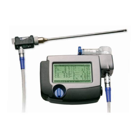
A 500
Combustion and Emissions Analyzer
Contents
Contents
1.
1.
Introduction ...............................
............................... 2
2.
2.
Getting Started ......................... 8
3.
3.
Operating the A 500 .............12
Operating the A 500
4.
Other Operations...................22
5.
Setup Screen Controls........28
6.
Maintenance ......................... 32
......................... 8
22
The Measure of Technology
7.
7.
Sensor Replacement
Sensor Replacement.................
8.
Parts and Service .......................
9.
9.
Sales/Service Centers
Sales/Service Centers................
10. Warranty..........................................
.......................................... 43
A.
A.
Appendix A - Peltier Cooler
Appendix A - Peltier Cooler ...... 44
35
35
.......................
40
40
................ 42
Advertisement
Table of Contents

Related Manuals for Wohler A 500


Summary of Contents for Wohler A 500
-
Page 1: Table Of Contents
Getting Started ......8 ......8 Sales/Service Centers....Sales/Service Centers ....42 Operating the A 500 Operating the A 500 .....12 10. Warranty..................43 Other Operations....22 Appendix A - Peltier Cooler ..44 Appendix A - Peltier Cooler Setup Screen Controls..28 Maintenance ...... -
Page 2: Introduction
PC for record keeping with just a touch of the screen. The operator can also upload customer information from their PC to the A 500 via the IRDA interface or can quickly and easily enter new customer information directly into the units memory using the alphanumeric keyboard feature of the touch-screen. - Page 3 The water trap and filters are conveniently located at the top of the analyzer for easy viewing, draining or changing. • The A 500 can operate from either an AC adapter, internal rechargeable batteries, or standard AA alcaline batteries. •...
- Page 4 1. Introduction A 500 1.2 Specifications Each A 500 Model Measures and Displays: Oxygen from 0.1 to 20.9% Carbon monoxide, hydrogen compensated from 0 to 4000 ppm Combustion air temperature from 0 to 257 °F (–20 to 125°C) Stack gas temperature from 32 to 1562 °F (0 to 850°C) Pressure: Stack draft in the range of ±16.00 inch H...
- Page 5 A 500 1. Introduction Operating Time: Approximately 12 hours of continuous operation with fully charged batteries. No time limit if using the AC adapter. Accuracy: ±0.3% ±5% of reading (0 and 4000ppm) ±10% of reading from 4001 and 16,000 ppm HIGH ±5% of reading or ±5 ppm, whichever is greater...
- Page 6 1. Introduction A 500 1.3 A 500 Components and Controls 1 1 4 Figure 1-1: A 500 Figure 1-1: A 500 Components Components 1. Power ON/OFF switch and CO sensor bypass 1. Power ON/OFF switch and CO sensor bypass 1. Power ON/OFF switch and CO sensor bypass 2.
- Page 7 1. Introduction A 500 Select fuel and re- Customer Information Current date (mm-dd) maining battery life Touch to enter customer and time (am/p p m Touch to enter fuel data input and management hour: minute) selection screen screen NGAS 04-06...
-
Page 8: Getting Started
2. Getting Started Important. Please ensure the batteries are fully charged before use. 2.1 Turning on the A 500 1. Turn the analyzer ON by rotating the OFF/ON switch to its “I” position (No. 1 Figure 1-1). This starts the pump motor. The LCD should briefly display the WÖHLER A500 logo, and software version number. - Page 9 These settings can be changed as described below. 2.4 Setup Screen Controls The Setup Screen is accessed by touching the SETUP key (lower left) after the A 500 is first turned ON and while its initial Turn-ON Screen (see Figure 2-1) is displayed.
- Page 10 2. Getting Started A 500 850 customers 4 loaded B100% 3.56 A 500 Touch to enter Date & Time Set up To return to USA Version 1.1 screen initial Turn On D&T MUNIT PRINT PROBE menu screen Touch to Touch to...
-
Page 11: Getting Started
To charge, plug the supplied AC adapter into a 120 VAC outlet, then plug the adapter’s DC output plug into the A 500’s power jack (No. 2, Figure 1-1). The A500 can be operated while its batteries are being charged when using the Fast Charger (suplied with unit) (P/N 9042). - Page 12 A 500 3. Operating the A 500 for a Combustion Efficiency Test NOTE: This chapter assumes that the user of the A 500 has the required techni- cal knowledge to properly identify the sampling point(s) for the type of equip- ment involved.
-
Page 13: Operating The A 500
3. Operating the A500 A 500 3.2 Select the Fuel type The A500 defaults to the most recently selected fuel as shown in the upper-left hand corner of the display. To select a different fuel, touch the Fuel name to display the Fuel Selection Screen (see Figure 3-2). - Page 14 3. Operating the A 500 A 500 3.3 The Combustion Test Screen = % Oxygen NGAS 04-06 Customer Name B 95% p03:36 = % Carbon Dioxide 4.0 % 68°F Effc = % Combustion Effi- 9.5 % 374°F ciency 82.6 % 17.4 %...
- Page 15 3. Operating the A 500 A 500 = Nitric Oxide NGAS 04-06 Customer Name B 95% p03:36 = Nitrogen Dioxide 18 ppm 19 ppm = Oxides of Nitrogen 6 ppm 6 ppm = Sulfur Dioxide 24 ppm 25 ppm REF = % Oxygen Reference...
- Page 16 3. Operating the A 500 A 500 2. Touch the displayed name of the combustion test value to be graphed. 3. A graph of the selected combustion test value is now be drawn from left to right on the screen. Along with the graph the display will also show the current numerical value.
- Page 17 PUM1. 3.7.1 Manual CO sensor Protection The A 500 has a high CO safety cutoff valve to protect the base 4000 ppm CO sensor from becoming saturated. If the detected CO level rises above 4000 ppm the A500 beeps and a message “CO:PROTECT ON”...
- Page 18 Removing condensation from the gas sample is critical for the proper operation and measurement accuracy of the unit. The A 500 has four condensate filters (Figure 3-11). The amount of condensation in the water trap / filter assembly should be checked before conducting a test and also observed during a test.
- Page 19 3. Operating the A 500 A 500 Figure 3-11: A 500 Gas Channel and Filter Protection e-mail: info@wohlerusa.com e-mail: info@wohlerusa.com http://www.wohlerusa.com http://www.wohlerusa.com...
- Page 20 When measuring NO2 or SO , the metal heat exchangers must be replaced with plastic versions in the A 500’s condensation block. It is also highly recommended that a Wöh- ler Peltier Cooler gas sample conditioner be attached to the probe assembly. The gas sample conditioner removes water vapor from the gas sample preventing the formation of water droplets inside the probe hose.
- Page 21 „PUM1“ if the unit is running or „PUM0“ if the unit is on hold. CO:PROTECT OFF: For units containing a CO High sensor (A 500 COH), the unit beeps and displays this message when the CO level drops from above 4000 ppm (depends on model) to below 1000...
-
Page 22: Other Operations
4. Other Operations of the A 500 4.1 Measuring Pressure In addition to draft measurements, the A 500 is also capable of measuring differential pressure using both the probe tip and the secondary pressure port (No. 14, Figure 1-1). Note: The probe’s secondary pressure port is attached to the pressure sensor’s negative port, causing a positive pressure to be displayed as a negative value. - Page 23 A 500. An operator can then recall a customer’s name at the job site and save test data under that name. 4.3 Using the Touch Screen Keyboard Entering data into the data management system is accomplished by using the analyzer’s Touch Screen Keyboard.
- Page 24 4. Other Operations A 500 select an existing customer name, refer to Section 4.6. 3. Once the desired customer name is displayed, touch the Enter key. 4. If data is already stored under that customer’s name, a warning message is display- ed asking to overwrite the current data.
- Page 25 4. Other Operations A 500 under that name. A “–” sign indicates that no data has been saved. 2. Do one of the following: Begin touching letters on the Touch Screen Keyboard that spell the customer’s name. The first name in memory that matches the letters entered will be displayed. Continue touching letters until the desired name appears.
- Page 26 DATA key to display the analyzer’s Data Screen. 4.11 Sending Data to a computer When prompted by the A 500 Data Exchange program to start IrDA communication, touch the SEND key to begin sending data from the A 500 to the computer. 4 loaded 4 loaded...
- Page 27 When data transfer is complete, the A 500 automatically returns to its Initial Turn-ON Screen. 4.13 Returning to Factory Defaults / Clearing Memory To return the A 500 to its factory default settings, and to clear memory of all customer names and test records. 1. Turn ON the analyzer.
-
Page 28: Setup Screen Controls
ON and while its Initial Turn-ON Screen (Figure 2-1) is displayed. 5.1 Setting Time & Date Do the following to set the A 500’s internal clock to the current time and date: 1. Turn ON the analyzer. 2. Touch the SETUP key as soon as the Initial Turn-ON Screen is displayed to show the Setup Screen. - Page 29 5. Setup Screen Controls A 500 5.4 Temperature Probe Calibration Factors (T-Stack & T-Air) All probe or combustion-air temperature probes have unique calibration factors that must be entered into the A500 NOTE: Failure to input the correct factors can result in inaccurate combustion test results.
- Page 30 5. Setup Screen Controls A 500 2. Touch the DISP (Display) key as soon as the Initial Turn-ON Screen is displayed to show a list of readings that currently appear on the Combustion Test Screen. 3. Touch NO to enter edit mode to remove or add a reading; then touch the reading to be removed or added.
- Page 31 After a new sensor is installed a record is made in the A 500 of the date of installation. The operator can easily access a screen to view the installed date of each sensor. To view the sensor dates: 1.
-
Page 32: Maintenance
Maintenance Filter Maintenance The A 500 has three filters which prevent soot particles and water from entering the analyzer. The water traps cotton filter and the water stop filter (No. 6 and 7, Figure 1-1) are located on the instrument, while a coarse particulate filter (No. 13, Figure 1-1) is located in the grip of the probe assembly. - Page 33 6. Maintenance A 500 6.1.3 Water Stop Filter The water stop filter blocks water from entering the analyzer. If this filter becomes saturated with water the analyzer’s pump will slow down and nearly stall. To replace this filter, first unlatch and remove the largest heat exchanger, and then use its hex tool to remove the screw that secures the water trap to the analyzer.
- Page 34 6. Maintenance A 500 Retaining Nut Probe End Probe Handle Figure 6-2: Cleaning the Probe Assembly Technical Service Hotline: 978-750-9876...
-
Page 35: Sensor Replacement
7. Sensor Replacement A 500 Sensor Replacement Sensor Diagnostics The sensor diagnostics allows the user to determine the status of the sensors. Do the following to enter the sensor diagnosis: 1. Turn ON the analyzer 2. Touch the DIAG (diagnosis) key as the initial Turn-ON screen is displayed 3. - Page 36 7. Sensor Replacement A 500 Sensor Replacement To access the sensor bank, press down on sensor cover botton on side of unit (see figure 7-1). press here to release sensor bank cover Figure 7-1: opening sensor bank high (4000ppm) or NO...
- Page 37 7. Sensor Replacement A 500 7.2.1. Replacing O2, NO, CO , NO or SO Sensor high Figure 7-3 Figure 7-4 Figure 7-5 1. unplug sensor ribbon cable (figure 7-3). 2. turn sensor 45° left (figure 7-4) 3. pull out sensor (figure 7-5) 4.
- Page 38 7. Sensor Replacement A 500 1. disconnect cable 2. release CO sensor by putting a small screw driver into the two xxxx of the plexiglas sensor bank (figure 7-6). 3. replace sensor (figure 7-7) and install in reverse procedure (figure 7-8, 7-9) 4.
- Page 39 7. Sensor Replacement A 500 Figure 7-9: CO-Sensor 7.3. Register Sensors in System Software Go to the Diagnosis screen like descibed in chapter 7.1. Press SENSOR key to reach the following screen. 02-03 SENSOR CHANGED ? 09:17 B100% 3.06 S t a t u s O K CO : 3.06...
-
Page 40: Parts And Service
4669 Plastic (used when measuring NO / SO Large 8668 Small 8669 8.3 Accessories Wohler TD 600 high speed printer 4130 heavy duty condensation adaptor 3635 AC Battery Charger (Fast) 9612 peltier cooler set with plastic heat exchangers 8031 Probe 39“... - Page 41 8. Parts and Service A 500 Combustion-Air Thermocouples: 2“ 9605 4“ with 5ft. cable 9651 11“ with 5ft. cable 9611 USB IR Data Exchange Kit (includes USB Ir Interface w/ Software) 9318 Peltier Cooler Sample Conditioner: Sample Conditioner Unit and Power Supply...
-
Page 42: Sales/Service Centers
9. Sales / Service Centers A 500 9. Sales / Service Centers United States, Massachusetts Wöhler USA Inc. 20 Locust Street, Suite 205 Danvers, MA 01923 Phone: 978-750-9876 Fax: 978-750-9799 Email: info@wohlerusa.com Canada, Ontario Carremm Controls Ltd. 3995 Sladeview Cres., Unit 6, Mississauga, Ontario, L5L 5Y1 Phone: 905-569-0335 Fax: 905-569-9712 Email: gyp@carremmcontrols.com... -
Page 43: Warranty
No part of this document may be photocopied, reproduced, or translated to another language without the prior written consent of Wöhler USA, Inc. Copyright © 2006, Wohler USA, Inc., all rights reserved. e-mail: info@wohlerusa.com e-mail: info@wohlerusa.com http://www.wohlerusa.com... -
Page 44: Appendix A - Peltier Cooler
Appendix A A 500 Appendix A – Peltier Cooler - Gas Sample Conditioner A.1 Introduction The Peltier Cooler—Gas Sample Conditioner consists of the Peltier Cooler and Power Supply (P/N 4637) and the optional Condensate Pump (P/N 4636) for long duration sampling. - Page 45 Appendix A A 500 Technical Data Peltier Cooler: Inlet Sample Dew Point 149 °F (65 °C) max. Outlet Sample Dew Point 18 °F (10 °C) min. below ambient Cooling Power 10 W Environment Temperature 32 to 104 °F (0 to 40 °C) Weight 8.5 oz (240 g)
- Page 46 Appendix A A 500 Operation When ready to conduct a combustion efficiency test, plug in the power supply of the Gas Sample Conditioner. The condensate pump should start running and the Peltier cooler’s red LED should begin to turn ON and OFF as the cooler is cycled. Note that the cooler’s operating time changes according to its temperature.
- Page 47 Appendix A A 500 Maintenance A.5.1 Probe The probe’s coarse filter needs to be inspected at regular intervals for dirt contaminati- on. Replace filter as necessary by first pulling out the Peltier cooler from the probe and then exchanging the filter with a new one.
- Page 48 A 500 Appendix A A.6 Replacement Parts Peltier Cooler & Power Supply: Complete Assembly with Power Supply 4637 AC Power Supply with 3-Wire Cord 21564 Plastic End Cap 9647 Filter Wadding 21208 Condensate Pump: Complete Assembly 4636 Water Trap 21089...
Need help?
Do you have a question about the A 500 and is the answer not in the manual?
Questions and answers