
Related Manuals for Wohler A 450


Summary of Contents for Wohler A 450
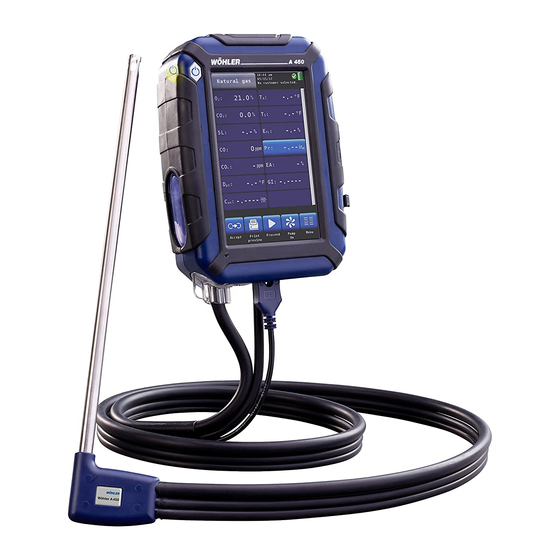
- Page 1 Operation Manual Flue Gas Analyzer Wohler A 450 Wohler A 450 L The Measure of Technology...
-
Page 2: Table Of Contents
Technical Data ..........13 Component Explanation ....14 Probes, sensors and filters ......16 Display ............18 Gas sampling path Wohler A 450 ....19 Getting started ........20 Activating the battery ........20 Tightness test ..........20 Charging the battery ........21 Connecting the flue gas probe .... - Page 3 Contents Print data ............. 31 Save data in the customer menu....32 Save data with the “Quick save” option ..33 Menu ............ 33 Device data ..........34 Ambient CO ..........35 Manifold Pressure ........35 Temperature Measurement ......37 Tuning Guide ..........
- Page 4 Contents Troubleshooting ........48 Maintenance ........49 11.1 Maintenance work ........49 11.2 Removing condensate ......... 50 11.3 Changing the filters ........51 11.3.1 Cotton filter ..........51 11.3.2 Water stop filter ........... 51 11.4 Sensor diagnosis and replacement ..... 52 11.5 Replacing the battery ........
-
Page 5: General Information
NOTE! Useful information Intended Use Use the Wohler A 450 for flue gas analysis and control of heating appliances and for the meas- urement of wood moisture. The analyzer should be used indoors only. The Wohler A 450 is not suitable for continuous operation. -
Page 6: Basic Features
General Information Basic features Device Basic equipment Wohler A 450 with Probe and hose as- WiFi. USB- and IR sembly with 1,5 m port hose Ambient Temperature Probe Charger with micro- USB-cable Li-Ion Battery Transport and stocking ATTENTION! Improper transport can harm the instrument. -
Page 7: Information On Disposal
General Information Analyzer Lock ATTENTION! For the transport deactivate the battery with the transport lock. The locking switch is located on the connection plate at the bottomside of the device. • Deactivate the battery by pushing the transport lock to the left to the “0” with a point- ed object (wire or pen). -
Page 8: Manufacturer
ATTENTION! In order to ensure the quality of the application and the measurement result, the ana- lyser may only be used with original Wohler accessories and original Wohler spare parts. This applies in particular to legally regulated measurement tasks ATTENTION! Do not expose the instrument to moist flue gas, if it has been exposed to temperatures below 0°C for a certain time. -
Page 9: Specifications
Specifications Specifications Readings Oxygen (O ) concentration in flue gas Display Volume % referenced to dry flue gas Measurement electrochemical sensor principle Range 0,0 to 21,0 % Accuracy ± 0,3 Vol. -%... - Page 10 Specifications Carbon monoxide (CO 100.000 ppm) in flue gas (only Wohler A 450 L, article 4672 Display Volume ppm referenced to dry flue gas Meas. principle Electrochemical sensor, H2 compensated Range 0 to 100.000 Vol. ppm, resolution 1 Vol.-ppm Accuracy ±...
- Page 11 Specifications Nitrogen monoxide (NO ) in flue gas (option) Display Volume ppm referenced to dry flue gas Measurement electrochemical sensor principle Range 0 to 3,000 Vol. ppm resolution 1 Vol.-ppm Accuracy ±5 vol. ppm (<100ppm), otherwise 5 % of reading Chimney draught / differential pressure (PD) Display Pascal...
-
Page 12: Calculated Values
Specifications Calculated Values Calculated Value Explanation Efficiency /SL Efficiency and losses in accordance to ASME standards ETA/QS Efficiency and losses in accordance to European standards (0,0 to 120%) in Vol. -% Range 0 – CO , resolution 0.1 % 2max , SO ;... -
Page 13: Technical Data
Specifications Technical Data Description Data Power supply Rechargeable Lithium-ion battery 3.7 V, 2250 mAh, charg- ing via USB Operation time Approx. 6,5 h (depending on the operating mode and the display backlight) Charging time for a full Approx. 3 hours charge Charging cycles of the After 500 charging cycles, at least 70% of the capacity are... -
Page 14: Component Explanation
Component Explanation Component Explanation On/Off condensate trap Connection plate for temperature, pressure, Gas probe connection Fig. 2: Front view of the analyzer... - Page 15 Component Explanation Fig. 3: Connection plate on the bottom of the unit Connections on the bottom of the unit Lock Battery, cf. chapter 4.1 USB-port for data transfer and charging IR interface for thermal printer Gas temperature Ambient Air Temperature Positive pressure Negative pressure Speaker for alarm signals...
-
Page 16: Probes, Sensors And Filters
Fig. 4: Flexible capillaries If you frequently do measurements on cogenera- tion units, please use the external Wohler CHP- Filter, that has to be attached to the probegrip Wohler A 450. Occasional measurements on co- generation units (maximum 50 measurements) - Page 17 Component Explanation Combustion air temperature probe Wohler A 450 , 185 mm Fig. 63: combustion air temperature probe Hoses for pressure measurement...
-
Page 18: Display
Component Explanation Display The Wohler A 450 is operated via Touchscreen. The measurement menu is similar to the one of a smartphone. A fingertip on the icon starts the correspondent measurement mode. The active icons are graphically emphasized. If there is a bar on the right of the display, the display can be scrolled by pulling it with the finger. -
Page 19: Gas Sampling Path Wohler A 450
Component Explanation Gas sampling path Wohler A 450 Fig.17: Gas sampling path Wohler A 450 with flue gas probe 250 mm The sensors are protected against condensate by a three-step-filter conditioning: The first step is the coarse filter in the probe handle. Most of the particles will be re- moved from the sample. -
Page 20: Getting Started
Getting started Getting started • Activating the battery Before first use: Activate the battery by push- ing the battery lock with a sharp object (paper clip or other slim wire) to the right, cf. adjacent figure. The locking switch is located on the connection plate at the bottom of the unit. -
Page 21: Charging The Battery
If the battery symbol is red, the display illumina- tion is automatically reduced to save energy. In this case, charge the battery or use the Wohler A 450 in mains operation. •... -
Page 22: Connecting The Flue Gas Probe
Getting started Connecting the flue gas probe • Attach the wide gas hose to the gas connec- tion (1) • Attach the small gas hose to the positive pres- sure connection (2) . • Attach the temperature plug tot he tempera- ture connection T (3). -
Page 23: Using The Analyzer
Long press the ON/OFF-key for 3 seconds to turn the analyzer off. Calibration Immediately after the device has been switched on, the Wohler A 450 will start to calibrate the sensors with fresh air. This calibration process will take 60 sec. Note! The gas probe may not be located in the flue gas tube during the calibration. - Page 24 Click on the "Data Exchange” icon to finish the Data Exchange hotspot search and enter the data exchange mode. In this mode data can be exchanged be- tween the Wohler A 450 and the PC via USB or Bluetooth. Opens the main menu. Only those submenus are Menu available which can be started without hotspot search.
-
Page 25: Measuring
Using the Analyzer Measuring After the 60 seconds calibration procedure the analyzer will display the main combustion efficien- cy test screen. 5.3.1 Readings screen Al readings (measured and computed values) will be shown continuously in the readings segment. NOTE! The user can change the order of the values. He can also select the unit of some of the values (see chapter 7.6) Up to 14 values can be shown on screen. - Page 26 Using the Analyzer Possible units Measured and computed values: Vol.-% Oxygen content Vol.-% Carbon dioxide content Flue gas loss ppm; mg/m Carbon monoxide, referred to dry flue gas, diluted value ppm, mg/m , mg/kWh, mg/MJ Carbon monoxide, corrected (air free) kg/m or kg/kg (depending on Condensate qty.
-
Page 27: Selecting The Fuel
Using the Analyzer 5.3.2 Selecting the fuel The selected fuel is shown in the topline on the left of the readings screen. • Click on the fuel key to enter the fuel options menu. Optional fuels as below: Natural gas, Fuel Oil 2, Fuel Oil 4, Fuel Oil 6, Bio- fuel, LPG, Propane, Kerosene, Digester Gas, Coal, Wood, Pellets and four user defined fuels NOTE! -
Page 28: Options
Using the Analyzer In the readings screen a click on one of the icons 5.3.4 Options at the bottom offers the following options: • Graph A click on the Graph icon generates a graph of the measured values. • Above the graph the measured value, which is presented in the graph, is indicated as a num- ber. - Page 29 The sample pump continues. • Press the Start/Stop button of the probe han- dle to stop the measurement and hold the val- ues. (The sample pump continues.) NOTE! Only the Wohler A 450 is equipped with a Start/Stop button.
- Page 30 Using the Analyzer • Pump off Click on "Pump OFF" to turn off the gas pump and the CO protection pump. • Pump on Click on "Pump on" to turn on the gas pump. Accept The “Accept” icon will only appear if the meas- urement is stopped.
-
Page 31: Readings Menu
Fig. 14: Readings Menu • Delete data Click on the “Delete data” icon to delete the selected data. • Print data Click on the “Print preview” icon to print the selected information on the Wohler TD 100 Thermoprinter. -
Page 32: Save Data In The Customer Menu
IR interface of the analyzer. After printing, the analyzer will enter the meas- urement mode again. Fig. 16: Printing the readings of the Wohler A 450 on the Thermoprinter Wohler TD 100. • Save data in the cus- Click on the “Save” icon to save a customer record. -
Page 33: Save Data With The "Quick Save" Option
Menu Save data with the If the quick save option is activated in the Setup- Menu (see Chapter 7.6), the analyzer will auto- “Quick save” option matically save the measurement records under a new customer. The customer name will be the measurement date and the measurement time. -
Page 34: Device Data
Menu Device data In the “Device data” screen the user can enter information about the heating system. He can save this information together with the readings in the customer folder. • Select a parameter. Fig. 19: “Device data” screen • Enter the correspondent information. -
Page 35: Ambient Co
Menu Ambient CO The option 'Ambient CO' offers a graphical assist- ed ambient CO test. The current ambient CO concentration is shown over the elapsed measurement time. The figure on the left shows an 'Ambient CO' test over a time period of 230 seconds and the current CO level is 2 ppm. - Page 36 Menu The options in the “Manifold Pressure” mode screen are: • Option “Cancel”: click “Cancel” to exit the “Manifold Pressure” test and return to the main menu. • Option “New”: click “New” to clear the graph and all captured readings and start a new “Manifold Pressure”...
-
Page 37: Temperature Measurement
Menu • Temperature To measure the temperature click on the “Temperature” icon in the main menu screen. Measurement NOTE! Make sure you connect the Ambient Air Plug, see Fig. 5. The options in the “Manifold Pressure” mode screen are: • Option “Cancel”: click “Cancel”... -
Page 38: Tuning Guide
Menu Tuning Guide In the "Tuning Guide" menu all combustion test related readings are presented in a graph over the excess air. The tuning guide offers an advanced guidance to the technician to properly adjust the burner. • In the main menu, click on the “Tuning guide” Tuning Guide icon. -
Page 39: Setup
Menu SETUP In the setup-menu the user can adjust the screen or the measurement process. In order to see all parameters, scroll to the top or the bottom of the screen by sweeping the left column with a finger. • In the main menu, click on the setup icon. -
Page 40: Option "Date
Menu 7.6.1 Option "Date" Change the current date of the analyzer's internal calendar with day, month and year. 7.6.2 Option "Time" Change the current time of the analyzer's internal clock (24 h mode) with hours and minutes. 7.6.3 Option “Date format” Select a date format. - Page 41 Menu Mode „OFF“ It is not possible to use the Wohler A 450 App. Mode „Direct connection“ If you do not have access to a router network, select Direct Connection. In this case the analyzer will create its own wire- less network.
- Page 42 Menu Network password that you have to enter in your mobile device. The password (factory set- ting) is 12345678. • Click on „Key“ to change the password. • Enter a new password (min. 8 figures, max. 24 figures) • Confirm with OK. Note! You have to confirm the settings with OK, be- fore you can establish the WLAN connection to...
-
Page 43: Option "Quick Save
• Open the Wohler A 450 App. • In the App, click on “Connect device”. The App will now connect to the Wohler A 450. 7.6.8 Option “Quick save” If the quick save option is activated, the analyzer will automatically save the meas- urement records under a new customer. -
Page 44: Signals
For this reason unau- thorized persons cannot calibrate the ana- lyzer and incorrect settings are avoided. The calibration of the analyzer is allowed to trained personnel ONLY. Please contact Wohler for more information. -
Page 45: Customer Data
Customer data Customer data The analyzer allows to save the values in different fireplace folders. You can assign a fireplace or several fireplaces to a customer. Each customer and each fireplace has its own number. • Set up a new customer There are two possibilities: 1. -
Page 46: Save Records
• Save records In the Readings menu (see chapter 6) click on the Save-icon to save all marked measurement records under a customer and a fireplace. The analyzer will enter the customer menu. The customer menu shows a list of all customers. -
Page 47: Search Function : Customer,Device, Customer Number, Device Number
• Search function : In the customer menu click on the “Find cus- tomer” iconcus. customer,device, customer number, device number • Enter any part of the customer name. At the bottom of the display the first result will be shown. Click on the arrow key to see the other results and select the customer. -
Page 48: New Customer
With the Wohler A 450 Sorftware it is possible to Data exchange exchange the data with the PC via USB or WLAN. with the PC NOTE! The data transfer and the functions of the Software are explained in the Manual Wohler A 450 PC Software. Troubleshooting Problem Possible reason... -
Page 49: Maintenance
Maintenance Maintenance Proper operation of the Wohler A 450 requires regular maintenance. 11.1 Maintenance work Interval Maintenance work If filter warning Change water-stop filter appears in the display. Once a year Return analyzer for check and calibration to a Wohler certi-... -
Page 50: Removing Condensate
Maintenance 11.2 Removing condensate The condensate will be collected in the condensate trap. To remove the condensate follow the steps below: • Turn the condensate 90° to the left and pull it out of the analyzer. Fig. 37: Pulling the condensate trap out of the analyzer Fig. -
Page 51: Changing The Filters
Maintenance 11.3 Changing the filters If the cotton filter or the water stop filter are clogged, a filter warning will appear at the top of the display. • In this case check the filter and change it if necessary. After the filter has been changed the warning will disappear. -
Page 52: Sensor Diagnosis And Replacement
The sensors can be changed in the factory or by an authorized service point. The user can also change the sensors himself. The Wöhler A 450 has an advanced electronic self diagnosis program. You can enter the diagnosis screen directly after having switched on the analyzer during self check and calibration . - Page 53 Maintenance • The diagnosis screen shows the sensor status (OK or NOT OK) and the firmware version. • After a click on the sensor key, detailed infor- mation about the sensor status will appear in the display. • After a click on the instrument key, detailed information about the analyzer will appear in the display: Version, serial, WLAN module, production date, calibration date, hours of op-...
- Page 54 Maintenance NOTE! If the user himself replaces the sensors, the sensor date shown in the diagnosis menu will update automatically. Replace the sensor as follows: • Power off the analyzer. • Loosen the 2 screws of the cover with a cross- headed screwdriver.
- Page 55 Maintenance Hose of the gas path Battery Holder sensor sup- port Fig. 44: Bottom of the analyzer with cover removed • Cautiously remove the transparent hose of the gas path from the holders. • Cautiously remove the sensor support from the analyzer.
- Page 56 Maintenance • Replacing the O Sensor Remove the 2-pin connector of the O sensor. • Replace the O sensor by a new one. • Plug the new connector to the original place. • Plug the O sensor to the board. NOTE! The hose of the gas path can stay connected to the gas pump.
- Page 57 Maintenance Fig. 47: Sensors plugged to the board. Top down: O , CO and NO (option) • Place the sensor support on the sensors again. • Install the hose of the gas path correctly in the holders. CAUTION! Take care not to bend the hose. •...
- Page 58 Maintenance • After a change of the CO-sensor, you must enter the calibration values in the calibration menu. • Switch on the analyzer. • In the main menu, click on the calibration icon. • Enter the Code 4798 • Click on Calibrate CO-sensor. •...
-
Page 59: Replacing The Battery
10 minutes and consult a doctor immediately! 11.5.1 Replacing the battery The Wöhler A 450 is equipped with a rechargeable lithium ion battery 3.6 V, 2250 mAh. Only after a long working period the battery has to be changed. In this case send the analyzer to your dealer or change the battery as follows: •... -
Page 60: Six-Monthly Check
Six-monthly check • Replace the cover and lock it. • Secure the cover with the three screws. 12 Six-monthly check The analyzer has to be checked every 6 month by a service point which is officially au- thorized. The prescription VDI 4208, page 2 specifies the minimum requirements. The following tests have to be performed: ·... -
Page 61: Guaranty And Service
If used properly, the warranty period for the Wohler A 450 will be 48 month from the date of sale. If used properly, the warranty period for the W0hler A 450 L will be 24 month from the date of sale. -
Page 62: Declaration Of Conformity
Flue gas analyzer model number: Wöhler A 450 / Wöhler A 450 L complies with the key safety requirements set down in the guidelines of the Council for the Harmonization of the Legal Requirements of the Member States in relation to the electromagnetic compatibility 2014/30/EG and the low voltage 2014/35/EG. -
Page 63: Accessories
Wöhler Clamping Cone for probes 8 mm Ø Art. n° 2494 Wöhler PTFE Cone for probes 8 mm Ø Art. n° 2463 PC Software Wöhler A 450 Art. n° 6595 Spare parts and consumables Water Stop Filters, 3 pcs. Art. n° 9621 Cotton Filters, 150 pcs. - Page 64 Gneisenaustr.12 www.woehler.de 80992 München Tel.: +49 89 1589223-0 Fax: +49 89 1589223-99 sued@woehler.de Czech Republic Wohler USA Inc. Wöhler Bohemia s.r.o. 5 Hutchinson Drive Za Naspern 1993 Danvers, MA 01923 393 01 Pelhrimov Tel.: +1 978 750 9876 Tel.: +420 565 323 076 Fax.: +1 978 750 9799...
Need help?
Do you have a question about the A 450 and is the answer not in the manual?
Questions and answers