
Related Manuals for Wohler A 550 INDUSTRIAL


Summary of Contents for Wohler A 550 INDUSTRIAL
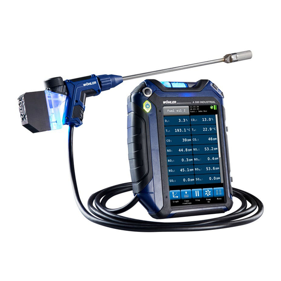
- Page 1 Operation Manual Portable Flue Gas Emissions Analyzer Wohler A 550 INDUSTRIAL The Measure of Technology GlobalTestSupply www. .com Find Quality Products Online at: sales@GlobalTestSupply.com...
-
Page 2: Table Of Contents
Setting up the instrument ....17 Component Explanation ......17 Probes and sensors ........20 Tightness test ..........23 Display ............24 Gas sampling path Wohler A 550 INDUSTRIAL ..........25 Getting started ........27 Charging the battery ........28 Connecting the probe and cable-hose assembly ............. - Page 3 General Information 6.3.3 Setting the fuel parameters ......38 6.3.4 Options ............38 Readings Menu ........41 Delete data ..........42 Print data ............. 42 Save data in the customer menu....43 Save data with the “Quick save” option ..43 Mesuring the Air speed and the Volume Flow of the flue gas ....
- Page 4 General Information Troubleshooting ........72 Maintenance ........73 13.1 Maintenance work ........73 13.2 Replacing the filters ........73 13.2.1 Coarse Filter ..........74 13.2.2 Removing condensate ......... 74 13.2.3 Replace cotton filter........75 13.2.4 Water Stop Filter ......... 75 13.3 Sensor diagnosis and replacement .....
-
Page 5: General Information
General Information General Information Operation Manual Infor- This operation manual allows you to work safely with the Wohler A 550 INDUSTRIAL. Please keep mation this manual for your information. The Wohler A 550 INDUSTRIAL should be em- ployed by professionals for its intended use only. -
Page 6: Basic Features
General Information Basic features Device Basic equipment (other configurations are possible) Wohler A 550 , NO, CO , NO High INDUSTRIAL sensor Probe and hose as- sembly with 3,000 mm hose Modular Flue Gas Probe 1,000 mm with sinter filter... -
Page 7: Information On Disposal
To open the probe compartment pull down • probe handle the snap closure under the black probe handle. Snap closure Fig. 1: Wohler A 550 INDUSTRIAL with open probe compartment ATTENTION! Lock the For the transport deactivate the battery with the analyzer transport lock. -
Page 8: Manufacturer
ATTENTION! In order to ensure the quality of the application and the measurement result, the ana- lyser may only be used with original Wohler accessories and original Wohler spare parts. This applies in particular to legally regulated measurement tasks. ATTENTION! Do not expose the instrument to moist flue gas, if it has been exposed to temperatures below 0°C for a certain time. - Page 9 Features and functions 1,000 data sets USB and infrared interface Bluetooth interface Fresh air pump GlobalTestSupply www. .com Find Quality Products Online at: sales@GlobalTestSupply.com...
-
Page 10: Specifications
Specifications Specifications Readings Oxygen (O ) concentration in flue gas Display volume % referenced to dry flue gas Measurement electrochemical sensor principle Range 0.0 to 21.0 % Accuracy ± 0.3 Vol. -% Carbon monoxide in flue gas (CO 100,000 ppm) Display volume ppm referenced to dry flue gas Measurement... - Page 11 Specifications Carbon dioxide concentration (CO ) in flue gas, NDIR Display Carbon dioxide concentration Measurement NDIR principle Range 0 …40 Vol. % Accuracy 0…6 Vol. %: ±0,3 Vol. % 6…40 Vol. %: ±5 % of reading Hydrogen sulfide concentration H S in flue gas Display volume ppm referenced to dry flue gas...
- Page 12 Specifications Nitrogen dioxide concentration (NO ) in flue gas Display volume ppm referenced to dry flue gas Measurement electrochemical sensor principle Range 0 to 1,000 Vol. ppm (continuously up to 200 vol. ppm); resolution 0.1 vol. ppm Accuracy ±5 vol. ppm (<100ppm), otherwise 5 % of reading Sulfur dioxide (SO ) in flue gas (option) Display...
- Page 13 Specifications Flue gas temperature (T Display °C Measurement Thermocouple (NiCr-Ni) principle Range -20.0 °C to 800.0 °C, resolution 0.1 °C Accuracy 0 - 133 °C ± 2°C; 133 to 800 °C: 1.5% of reading Flue gas temperature (T ) High Temperature Probe Display °C / °F Measurement...
- Page 14 Specifications Wood moisture Reading water mass related to the absolute dry fuel mass Measurement resistance measurement principle Range 10.0 to 40.0 %, resolution 0.1 % Accuracy 40 % of reading wood 5 to 25° C temperature lifetime of the Depending on the frequency of utilization electrodes The electrodes will work correctly, if there is no surface damage or bending.
-
Page 15: Calculated Values
Specifications Calculated Values Calculated Value Explanation Efficiency /SL Efficiency and losses in accordance to ASME standards ETA/QS Efficiency and losses in accordance to European standards (0.0 to 120%) in Vol. -% Range 0 – CO , resolution 0.1 % 2max , SO ;... -
Page 16: Technical Data
Specifications Technical Data Description Data Power supply Lithium-Ion, rechargeable battery 3.7 V, 6700 mAh, charges via USB Battery Operation time Approx. 7 h (depends on operation status and display illu- mination) Charging cycles of the After 500 charging cycles, at least 70% of the capacity are batteries: still available Storage Temperature... -
Page 17: Setting Up The Instrument
Setting up the instrument Setting up the instrument Component Explanation Fig. 3: Device front Explanation On/off-button Condensate trap Opening handle for the condensate trap Probe compartment Opening handle for the probe compart- ment NOTE! Open the probe compartment by pulling down the opening handle. - Page 18 Setting up the instrument Fig. 4: Probe handle with gas probe 295 mm Probe probe handle: ON/Off-Key Gas Probe 10 Union nut 11 Plexiglas plug with Coarse Filter On/Off-key (8) It is possible to start and stop the measurement with the On/Off-key (8) of the probe handle. This permits an easy handling in difficult measurement conditions.
- Page 19 Deactivate the battery by pushing the • transport lock to the right (see figure opposite) with a pointed object (wire or pen). Fig. 8: Interior of the probe compartment Wohler A 550 INDUSTRIAL GlobalTestSupply www. .com Find Quality Products Online at:...
-
Page 20: Probes And Sensors
Setting up the instrument Probes and sensors NOTE! Only the Flue Gas Probe 1,000 mm and the Ambi- ent Temperature Plug are included in the Basic Set. Other hoses and probes mentioned in this section can be purchased as accessories. Flue gas probe 1,000 mm to take emission meas- urements, even with heavy dust loads in difficult to reach locations. - Page 21 Setting up the instrument S-tube probe for measuring the flow speed Fig. 12: S-tube probe Flexible capillaries for the 4 PA test Fig. 13: Flexible capillaries GlobalTestSupply www. .com Find Quality Products Online at: sales@GlobalTestSupply.com...
- Page 22 Setting up the instrument Ambient Temperature Probe 185 mm Fig. 14: Ambient Temperature Probe Wood Moisture Probe Fig. 15: Wood Moisture Probe Spillage Probe Fig. 16: Spillage Probe GlobalTestSupply www. .com Find Quality Products Online at: sales@GlobalTestSupply.com...
-
Page 23: Tightness Test
Setting up the instrument Tightness test Before the tightness test connect the gas probe (see chapter 5.2). Proceed as follows: Squeeze the ball pump (part 1). Plug the ball pump (part 1) on the gas probe (part 2) Release the ball pump. After the ball pump has been released, it may not fill with air or only fill very slowly. -
Page 24: Display
Setting up the instrument Display The Wohler A 550 INDUSTRIAL is operated via Touchscreen. The measurement menu is similar to the one of a smartphone. A fingertip on the icon starts the correspondent measurement mode. The active icons are graphically emphasized. -
Page 25: Gas Sampling Path Wohler A 550 Industrial
Setting up the instrument Gas sampling path Wohler A 550 INDUSTRIAL Fig. 19: Gas sampling path Wohler A 550 INDUSTRIAL GlobalTestSupply www. .com Find Quality Products Online at: sales@GlobalTestSupply.com... - Page 26 Setting up the instrument The Wohler A 550 INDUSTRIAL has two pumps. A sample pump sucks the flue gas through the probe and the cable hose. A purge pump pumps fresh air to all sensors during the calibration phase. As the sample pump is cut-off during the calibration, the hotspot can already be searched during this time.
-
Page 27: Getting Started
• probe handle the snap closure under the black probe handle. Snap closure Fig. 20: Wohler A 550 INDUSTRIAL with open probe compartment Before the first start up activate the batteries • by pushing the transport lock in the probe compartment (see Fig. -
Page 28: Charging The Battery
If the battery symbol is red, the display illumina- tion is automatically reduced to save energy. In this case, charge the battery or use the Wohler A 550 INDUSTRIAL in mains operation. Fig. 22: USB port at the bottom •... -
Page 29: Connecting The Probe And Cable-Hose Assembly
Getting started Connecting the probe and cable-hose assembly Fig. 23: Probe handle with gas probe 295 mm Probe handle: ON/Off-Key (only Wohler A 550 INDUS- TRIAL) Gas probe Union nut Plexiglas plug with coarse filter 5.2.1 Connecting the probe Use different probes depending on the measurement to be done. Connect the probe as... - Page 30 Getting started Connecting the gas probe 1000 • Remove the blue union nut from the probe handle. • Remove the yellow plug and the grey union nut from the probe. Fig. 25: Removing the plug from the gas probe 1,000 mm Plug the probe on the probe handle.
- Page 31 Getting started The gas probe 1,000 mm has an in-stack sinter-fil- ter for dust protection. It removes dust (> 20 ym) from the sample gas to protect the analyzer against heavy dust loads. Before measuring make sure that the screw •...
-
Page 32: Connecting The Hose To The Analyzer
Snap closure Close the probe compartment as follows: Pull • down the snap closure, lower the probe han- Fig. 27: Wohler A 550 INDUSTRIAL with open probe compartment dle and engage the snap closure. Fig. 28: Female connector for the probe... -
Page 33: Using The Analyzer
Using the Analyzer Using the Analyzer ATTENTION! Before use, always test if the instrument is in a proper condition as described in chapter 4 . Perform a tightness test according to chapter 4.3 Turning the analyzer on and off Press the ON/OFF key shortly to turn ON the •... - Page 34 Data Exchange hotspot search and enter the data exchange mode. In this mode data can be exchanged be- tween the Wohler A 550 INDUSTRIAL and the PC via USB or Bluetooth. Opens the main menu. Only those submenus are Menu available which can be started without calibration.
-
Page 35: Measuring
Using the Analyzer Measuring Upon conclusion of the 60 seconds calibration procedure and the hotspot search the analyzer will display the main combustion emission test screen. At the same time the purge pump will turn off and the sample pump will turn on. 6.3.1 Readings screen Al readings (measured and calculated values) will... - Page 36 Using the Analyzer Possible units Measured and computed values: Vol.-% Oxygen Vol.-% Carbon dioxide Flue gas loss ppm; mg/m Carbon monoxide, referred to dry flue gas, diluted value ppm, mg/m , mg/kWh, mg/MJ Carbon monoxide, corrected (air free) kg/m or kg/kg (depending on Condensate qty.
- Page 37 Using the Analyzer Possible units Measured and computed values: ETA/QS Efficiency and losses in accordance to European standards (0.0 to 120%) Differential Pressure Pa, hPa, mbar, mmH O, inwc, psi λ Theoretical air/ excess air Excess air m/s, ft/min Speed Flow /h, m /s, cfm...
-
Page 38: Selecting The Fuel
Using the Analyzer 6.3.2 Selecting the fuel The selected fuel is shown in the topline on the left of the readings screen. Click on the fuel key to enter the fuel options • menu. Optional fuels as below: Natural gas, Fuel Oil 2, Fuel Oil 4, Fuel Oil 6, Bio- fuel, LPG, Propane, Kerosene, Digester Gas, Coal, Wood, Pellets and four user defined fuels NOTE! - Page 39 Using the Analyzer • Above the graph the measured value, which is presented in the graph, is indicated as a num- ber. Select the value to be presented with the ar- • row keys. The options in the graph mode are as follows: Click New to start a new measurement.
- Page 40 Using the Analyzer Stop Click Stop to stop the measurement and hold • the values. The sample pump continues. Press the Start/Stop button of the probe han- • dle to stop the measurement and hold the val- ues. (The sample pump continues.) Pumps off Click on "Pumps OFF"...
-
Page 41: Readings Menu
Readings Menu Readings Menu If the user accepts a record, the analyzer will en- ter the readings menu automatically. It is also pos- sible to enter the readings menu by clicking on the readings icon in the main menu. In the readings menu a list with all possible measurements and tests is shown. -
Page 42: Delete Data
Click on the “Delete data” icon to delete the selected data. Print data • Click on the “Print preview” icon to print the selected information on the Wohler TD 100 Thermoprinter. A print preview will appear. Click on the “Cancel” icon, if you do not want •... -
Page 43: Save Data In The Customer Menu
Mesuring the Air speed and the Volume Flow of the flue The Wohler A 550 INDUSTRIAL can measure air speed and volume flow by using the differential pressure sensor. Prandtl and S-Tube probes are available in different lengths to measure air speed for example inside the stack. - Page 44 Mesuring the Air speed and the Volume Flow of the flue gas • In the Setup-menu select “Flow parameter” Enter the cross-section of the pipe. • Fig. 37: Setup > Flow Parameter Connect an S-tube probe as follows: • - plug the two pressure hoses on the pressure connectors of the analyzer.
-
Page 45: Measuring The Air Speed
Mesuring the Air speed and the Volume Flow of the flue gas 8.1.1 Measuring the Air Speed In calm air, switch on the analyzer and wait 60 • seconds. Static pressure When closed, the S-tube can be inserted • through the measurement opening into the gas flow. - Page 46 Mesuring the Air speed and the Volume Flow of the flue gas GlobalTestSupply www. .com Find Quality Products Online at: sales@GlobalTestSupply.com...
-
Page 47: Menu
Menu Menu Click on the main “Menu” icon to enter the • Menu main menu. In the main menu you can select the different measurement options or the setup-menu or the cal- ibration menu. The lower icon bar shows the “Customer” (see chapter 10) and the “Readings”... -
Page 48: Device Data
Menu Device data In the “Device data” screen the user can enter in- formation about the heating system. He can save this information together with the readings in the customer folder. Select a parameter. • Fig. 42: “Device data” screen •... -
Page 49: Ambient Co
Menu Ambient CO The option 'Ambient CO' offers a graphical as- sisted ambient CO test. The current ambient CO concentration is shown over the elapsed measurement time. The figure on the left shows an 'Ambient CO' test over a time period of 230 seconds and the current CO level is 2 ppm. -
Page 50: Wood Moisture
Menu Wood moisture The Wohler A 550 INDUSTRIAL can perform a wood moisture test based on a re- sistance measurement. In order to obtain an exact measurement, the respective mate- rial will be considered. As the measured value depends on the material temperature, the meter will perform an automatic temperature compensation on the basis of the temperature entered by the user. -
Page 51: Connecting The Probe
NOTE! The result of the resistance measurement will be more exact, if the large wood moisture probe Wohler HBF 420 is used, because the needles of the probe can be inserted more deeply into the wood. Fig. 46: Wood moisture measurement with Probe Wohler HBF 420. - Page 52 Menu Selecting the type of wood • Click on the wood in the upper left corner of the screen. • A list with different woods will appear : The following woods can be selected. Maple, birch, beech, oak, ash, spruce, chestnut, pine, larch, linden, poplar, plane, fir, elm.
- Page 53 Menu Measuring the wood moisture • Split the wood log in the middle and perform the measurement immediately after that at the inside part of the log. The electrodes should penetrate into the wood • approx. 6 mm. ATTENTION! Insert the electrodes only if possible without ap- plying force.
-
Page 54: Spillage Test
1 Measurement of the condensation on the sensor board. 2 Temperature measurement NOTE! Connect the spillage probe Wohler A 550 INDUSTRIAL to the analyzer. • Plug the connector of the Spillage Probe Wohler A 550 INDUSTRIAL to the female con- nector at the bottom of the analyzer. - Page 55 Menu • Guide the probe along the areas to be in- spected. Fig. 51: Spillage test: Searching for con- densate The dew point will be indicated on a scale from 1 to 100. (0% = no condensation) In the display the user can observe on the graph, when condensation rises.
-
Page 56: Tuning Guide
Menu Tuning Guide In the "Tuning Guide" menu all combustion test related readings are presented in a graph over the excess air. The tuning guide offers an advanced guidance to the technician to properly adjust the burner. • In the main menu, click on the “Tuning guide” Tuning Guide icon. -
Page 57: Manifold Pressure
Menu Manifold Pressure • To perform a manifold pressure test click on the “Manifold Pressure” icon in the main menu screen. Connect a pressure hose to one of the pres- • sure connectors at the bottom of the analyzer . Fig. -
Page 58: Temperatures
Menu Temperatures • To measure the temperature click on the “Temperature” icon in the main menu screen. NOTE! Make sure you connect the Ambient Air Plug, see Fig. 11. The options in the “Manifold Pressure” mode screen are: Option “Cancel”: click “Cancel” to exit the •... -
Page 59: Pa - Test
Menu 4 Pa - Test The 4 Pa Pressure Test is a simple control of the depression limit 4 Pa. With the 4 Pa- Test the user controls if there is sufficient combustion air in the room where the fire place is installed. - Page 60 Menu How to perform the 4 Pa Pressure Test: Switch on appliance and all air conditioning (fan, dryer) with maximum power. Open an outside window or a door to the ref- erence room and test proper operation of the appliance, ensure that there are no backdraft conditions.
- Page 61 Menu The second capillary hose will stay uncut in the fireplace room. Click on "Start" to start the 4 PA-test. The meter will now record the pressure profile for 4 minutes. Open the window/door for about 30 seconds, so that the zero line can be registered. (Every 30 seconds an acoustic signal will sound.) Close the window/door for about 30 seconds, control depression.
- Page 62 NOTE! For the detailed procedure according to the Tech- nical Rules for Gas Installations (TRGI), working sheet G 625 (2009), it is necessary to replace the fireplace by the Wohler DP 600 (see manual Wohler DP 600). GlobalTestSupply www. .com Find Quality Products Online at: sales@GlobalTestSupply.com...
-
Page 63: Logger Measurement
Take measurement readings and save data 3 min purging Automatic shut down of the analyser When the logger configuration is completed the Wohler A 550 INDUSTRIAL will calculate the end- ing date and time of the measurement for infor- mation purposes. GlobalTestSupply www. - Page 64 Menu Fig. 58: schematic representation of a logger measurement Enter the start date and time • Enter the measurement interval, the interval • duration in the sample in the figure on the left is 10 seconds Enter the number of measurements (up to •...
- Page 65 Menu Long time measurements with For continuous long term measurements with in- the USB Peltier cooler terval < 8 min it is recommended to use the USB Peltier cooler. The peltier cooler will remove con- densate from the sample gas. During operation the condensate trap of the cooler needs to be emptied.
-
Page 66: Setup
Menu 9.10 SETUP In the setup-menu the user can adjust the screen or the measurement process. In order to see all parameters, scroll to the top or the bottom of the screen by draging the left col- umn with a finger. •... - Page 67 Change the order of the saved records between name or ID (Number) of the fireplace Option "NO calculation" In case the Wohler A 550 INDUSTRIAL is not equipped with a NO sensor the user can enter the NO percentage on which the calculation of the NO value is based.
- Page 68 Menu Option "Flow para” When a Prandtl or S-Tube is connected, the Wohler A 550 INDUSTRIAL measures the air speed for example inside the stack. In order to calculate volume flow the user has to enter the cross section. 4 Pa duration Here the user can determine how long the ana- lyzer shall log the pressure during the 4 PA- test.
-
Page 69: Calibration
The calibration of the analyzer is allowed to trained personnel ONLY. Please contact Wohler for more information. Customer data The analyzer saves data records by systems. A customer can have multiple systems like burners and boilers. -
Page 70: Save Records
• Enter the name and the number of the cus- tomer and the device. Confirm with OK. Fig. 63: Creating a new customer folder Save records • In the Readings menu (see chapter 7) click on 10.2 the Save-icon to save all marked measure- ment records under a customer and a device. -
Page 71: Search Function : Customer, System, Customer Number, Installation Number
10.3 Search function : • In the customer menu click on the “customer search” icon. customer, system, customer number, installation number • Enter any part of the customer name. In this case it is not necessary to observe the upper and lower case. -
Page 72: New Customer
With the Wohler A 550 Sorftware it is possible to exchange the data with the PC via USB or Blue- with the PC tooth. NOTE! The data transfer and the functions of the Software are explained in the Manual Wohler A 550 PC Software. Troubleshooting Problem Possible reason... -
Page 73: Maintenance
Maintenance Maintenance Proper operation of the Wohler A 550 INDUSTRIAL requires regular maintenance. 13.1 Maintenance work Interval Maintenance work After every Remove condensate from the combustion test coarse filter. Check the condensate trap and remove condensate and water if necessary. -
Page 74: 13.2.1 Coarse Filter
Maintenance 13.2.1 Coarse Filter Plexiglas plug A coarse filter located in the probe handle pre- • vents soot from entering the hose. After every measurement control if it is wet. Proceed as follows: Pull the plexiglas plug out of the probe handle. •... -
Page 75: 13.2.3 Replace Cotton Filter
Maintenance • Pull the condensate trap from the unit. Condensate outlet. • Remove the condensate cup from the conden- sate spiral. The condensate outlet remains in the cup. Spill the condensate out of the cup. • Condensate spiral Condensate cup Fig. -
Page 76: Sensor Diagnosis And Replacement
2 years The sensors can be changed by the customer or by an authorized service point or at the factory. The Wohler A 550 INDUSTRIAL has an advanced electronic self diagnosis program. You can enter the diagnosis screen directly after having switched on the analyzer during self check and calibration . - Page 77 Maintenance • The diagnosis screen shows the sensor status (OK or NOT OK) and the firmware version. • A click on the sensor opens a window with im- portant sensor information. Click on “Back” to start the search for the •...
- Page 78 Maintenance NOTE! If the "service" message appears, first turn the an- alyzer off and on again. After the analyzer has been turned on, it will automatically start to cali- brate the sensors with fresh air. Start the diagno- sis screen again. Only if the service message still appears on screen, the sensor will have to be changed.
- Page 79 Maintenance Battery Flexible conductor Connecting tube -sensor optional optional optional CO-sensor for gas channel sensor sensor sensor 2 pin connector of the O sen- Optional sensor: CO NDIR, SO S, NO, NO Fig. 73: Bottom of the analyzer without cover Slightly lift the left side of the sensor holder •...
- Page 80 Maintenance Replacing the O Sensor NOTE! See Fig. 73 for the position of the sensor. Remove the 2-pin connector of the O sensor. • Replace the O sensor by a new one. • • Plug the new 2-pin connector where the old one was.
- Page 81 Maintenance Replacing the other sensors NDIR, NO , SO S, NO, NOTE! See Fig. 73 for the position of the sensor. Pull the small locking mechanism (1) forward. • Take off the white flexible conductor (2). • Replace the sensor by a new one. Plug the flexible conductor in his place and •...
-
Page 82: Replacing The Battery
The Wohler A 550 INDUSTRIAL is equipped with a rechargeable lithium ion battery 3.7 V. Only after a long working period the battery has to be changed. In this case send the analyzer to your dealer or change the battery as follows: Switch off the analyzer. - Page 83 Maintenance • Pull out the battery plug and remove the bat- tery. • Install a new battery and plug in the battery plug. Fig. 76: Pulling out the battery plug Make sure that the connecting tube is in its • original position marked by the guiding hooks.
-
Page 84: Replacing The Electrodes Of The Wood Moisture Probe
Analyzer check 13.5 Replacing the elec- • Control if the electrodes are damaged. Take care that the distance between the electrodes trodes of the wood is 25 mm. moisture probe Broken or damaged electrodes can be ex- • changed by the user. Loosen the damaged electrodes with an appropriate tool (gripper, screw wrench or ring wrench). -
Page 85: Warranty And Service
· Warranty and Service Each Wohler A 550 INDUSTRIAL will be tested in all functions and will leave our factory only after extensive quality control testing. The final control will be recorded in detail in a test report and delivered with any unit. -
Page 86: Accessories For Wöhler A 550 Industrial
Wohler A 550 Gas Probe 295 mm P/N 9622 Wohler A 550 Flue Gas Probe 1,000 mm P/N 9695 Wohler A 550 Air Temperature Probe 280 mm, with 1.7 m cable P/N 5511 Wohler Velocity Probe Type S for Wohler A 550, to measure gas velocity P/N 5579 Pitot Tube, length 100 cm, 7 mm dia. - Page 87 Accessories for Wöhler A 550 Industrial Field Replacable Sensors NO sensor Wöhler A 550 P/N 5597 sensor Wöhler A 550 P/N 5598 sensor 100.000 ppm Wöhler A 550 P/N 5596 High sensor Wöhler A 550 P/N 5594 sensor Wöhler A 550...
Need help?
Do you have a question about the A 550 INDUSTRIAL and is the answer not in the manual?
Questions and answers