Table of Contents
Advertisement
Quick Links
Advertisement
Table of Contents

Related Manuals for Wohler TA 420


Summary of Contents for Wohler TA 420
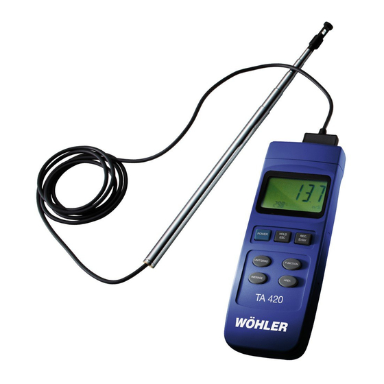
- Page 1 Operation manual Thermoanemometer Wöhler TA 420 The Measure of Technologie...
-
Page 2: Table Of Contents
General Information Contents Contents General Information ......4 Operation Manual Information ....... 4 Notes ............. 4 Intended Use ..........4 Scope of supply ..........4 Information on disposal ......... 5 Merchant ............5 Technical Data ........6 Design and Function ......9 Key assignments ........... - Page 3 General Information 12.2 Select the Temperature Unit ......20 Changing the Batteries ...... 21 System Reset ........21 Maintenance and Care ....... 21 Warranty and Service ......22 16.1 Warranty ............22 16.2 Service ............22 Accessories ......... 23 Declaration of conformity ....23...
-
Page 4: General Information
General Information General Information This operation manual allows you to work safely Operation Manual In- with the Wöhler TA 420 Thermoanemometer. formation Please keep this manual for your information. The Wöhler TA 420 Thermoanemometer should be employed by professionals for its intended use only. -
Page 5: Information On Disposal
General Information Information on disposal Electronic equipment does not belong into domes- tic waste, but must be disposed in accordance with the applicable statutory provisions. You may hand in any defective batteries taken out of the unit to our company as well as to recycling places of public disposal systems or to selling points of new batteries or storage batteries. -
Page 6: Technical Data
Technical Data Technical Data Description Data Size 203 x 76 x 38 mm Weight 515 g Probe length 280 mm to 940 mm Probe diameter 12 mm Screen LCD 58 mm x 34 mm Simultaneous display of the flow speed and the temperature Flow probe Glas-perl-thermistor... - Page 7 Technical Data Air velocity Description Data Units Meter per second (m/s) Kilometer per hour (km/h) Miles per hour (mile/h) Knot (knot) Feet per minute (ft/min) Range 0.2 – 20.0 m/s 0.7 – 72.0 km/s 0.5 – 44.7 m/s 0.4 to 38.8 knot 40 –...
- Page 8 Air temperature Description Data Units Degrees Celsius (°C), Fahrenheit (°F) Range 0 to 50 °C 32 °F to 122 °F Resolution 0.1 °C 0.1 °F Accuracy ± 0.8 °C ± 1.5 °F Additional Functions Description Data Data Hold Freezes the current readings Memory Recall Indicates the minimal...
-
Page 9: Design And Function
Design and Function Design and Function Key assignments Fig. 1: Keyboard 1 POWER key Switch on/off 2 HOLD/ESC key Hold the current value Leave the menu 3 REC/Enter key Recording function for maximum and minimum values Acknowledgement of adjustments 4 UNIT/ZERO key Selection of measuring unit Zero-point calibration 5 FUNCTION key... -
Page 10: Telescopic Bar With Sensors
Fig. 2: Probe Functional Principle The Wöhler TA 420 measures the flow velocity via a very small glass bead thermistor. The temperature compensation required for a precise measurement at different tempera- tures is automatically achieved via a separate thermistor which is installed below the flow sensor. -
Page 11: Preparation For Operation
Preparation for Operation Preparation for Operation CAUTION! Only use the device in the permitted temperature range. Avoid strong vibrations. CAUTION! Do not operate the device in the vicinity of strong electric fields. CAUTION! Never lay the device onto the user interface. - Page 12 Preparation for Operation • In order to be able to perform a flow meas- urement, push the protective cap (Fig. 2, part 4) completely downwards. . Both sensors must come into contact with ambient air. • Pull the telescopic bar to the required length Fig.
-
Page 13: Switch On
Switch On • Switch On Switch on the device by pressing the POWER key. The device will perform a self-diagnosis. After- wards the main display will show the flow data and - in the lower left-hand part - the temperature. •... -
Page 14: Measuring The Volume Flow
Measuring the Volume Flow Measuring the Volume Flow • Simple volume flow After switching on, press the FUNCTION key until the device is in the volume flow measur- measuring (current ing mode. The display will read CMM (cubic value) meter per minute) or CFM (cubic feet per mi- nute). -
Page 15: Input Of Area
Measuring the Volume Flow Input of Area In order to facilitate the volume flow measure- ment, you can manually input the cross-sectional area of the pipe opening or pipe to be measured To do so, proceed as follows: • Press the AREA key in the air volume flow mode (CMM or CFM). -
Page 16: Average Value Measurement
Measuring the Volume Flow The individual measuring points each can be rec- Average Value Meas- orded for system measurements in air ducts (trivi- urement al procedure) and the average value can be calcu- lated automatically. The average will directly be 0.000 shown on the display. -
Page 17: Volume Flow Measurement With A Measuring Funnel
Measuring the Volume Flow Volume Flow Meas- Measuring funnels (see accessories), can be used both with the determination of the current value urement with a Measur- (refer to item 8.1 and with the determination of the ing Funnel average (refer to item 8.3). In this case, the aver- age value measurement is to compensate fluctua- tions during measurement. - Page 18 Measuring the Volume Flow Depending on which funnel is used for measuring, the areas stated below are to be input in the TA 420 in accordance with Chapter 8.2: Measuring Item number Area to be funnel input K 150 53788 0.005 m K 120 53789...
-
Page 19: Zero Calibration
Zero Calibration • Zero Calibration Press the FUNCTION key in order to get into the flow velocity measuring mode. The dis- play will read the unit for the air velocity (m/s, ft/min, knots or mile/h). • Push the protective cap at the sensor head over the hot wire sensor until it is completely covered. -
Page 20: Adjustments
Adjustments Adjustments Before being able to make any adjustments at the device, the HOLD function and the REC function have to be deactivated as described in the relevant chapters. This means that the display must neither show HOLD nor REC. •... -
Page 21: Changing The Batteries
Changing the Batteries Changing the Batteries As soon as the battery icon appears in the upper left-hand display, the batteries have to be changed. • Loosen the Phillips screw at the battery compartment lid at the rear side of the de- vice and pull the lid off. -
Page 22: Warranty And Service
If used properly, the warranty period for the 16.1 Warranty Wöhler TA 420 will be twelve month from the date of sale. Batteries are not covered by this warranty. This warranty does not cover the freight and pack- ing costs when the device is sent to the factory for repair. -
Page 23: Accessories
Declaration of conformity The product product name: Thermoanemometer Model Wöhler TA 420 complies with the key safety requirements set down in the guidelines of the Council for the Harmonization of the Legal Requirements of the Member States in relation to the electromagnetic compatibility (2004/108/EG). - Page 24 Fax: +44 1223 281107 393 01 Pelhrimov e-mail: info@woehler.co.uk Tel.: +420 5653 49019 www.woehler.co.uk Fax: +420 5653 23078 info@woehler.cz Wohler USA Inc. France 5 Hutchinson Drive Wöhler France SARL Danvers, MA 01923 16 Chemin de Fondeyre Tel.: +1 978 750 9876 31200 Toulouse Fax.: +1 978 750 9799...
Need help?
Do you have a question about the TA 420 and is the answer not in the manual?
Questions and answers