Table of Contents
Advertisement
Quick Links
Download this manual
See also:
Operating Manual
Advertisement
Table of Contents

Related Manuals for Wohler A 400


Summary of Contents for Wohler A 400
- Page 1 Operation Manual Flue Gas Analyzer Wohler A 400 Wohler A 400 The Measure of Technology...
-
Page 2: Table Of Contents
Display and key setup ......... 14 Getting started ........15 Check battery status ........15 Connect the probe and hose assembly (Wohler A 400 only) ....... 17 Tightness test ..........17 Manifold pressure connector ....... 18 Using the Analyzer ......18 Key functions .......... - Page 3 Contents 5.4.10 Option 'SETUP' ..........30 5.4.11 Option 'CALIBRATION' ........ 32 Turning OFF the analyzer ......32 Troubleshooting ......... 33 Maintenance ........34 Maintenance work ........34 Removal of condensate ....... 35 Safety features and maintenance advice ..35 7.3.1 Filter light ............. 35 7.3.2 LT-filter ............
-
Page 4: General Information
NOTE! Usefull information Intended use Do not use the Wohler A 400 Flue Gas Analyzer for any other use than set out in this manual. The analyzers should be used indoors only. Use the Wohler A 400 for flue gas analysis of heating appliances, ambient CO and manifold pressure tests only. - Page 5 Wohler A 400 Probe and hose assembly Heavy duty carrying case Batteries Replacement filters Available sets may include: • rechargeable batteries and recharger • Wohler TD 600 high speed thermal printer • Wohler RP 72 Soot Pump • Ambient temperature probe 280...
-
Page 6: Transport
The carrying case can be purchased separately. Manufacturer Wöhler Messgeräte Kehrgeräte GmbH 41 Schützenstrasse Bad Wünnenberg, Germany, 33181 North American Wohler USA Inc. Headquarters 20 Locust Street Danvers, MA, 01923 Phone +1 (978) 750 9876 +1 (978) 750 9799 Email info@wohlerusa.com... -
Page 7: Specifications
Range 0 … 4,000 ppm Resolution 1 ppm Accuracy ± 5 % f.m., absolute ± 20 ppm Nitrogen monoxide (NO 1,000 ppm) (only A 400 Sensor type electrochemical Range 0 … 1,000 ppm Resolution 1 ppm Accuracy ± 5 ppm (<100 ppm),... - Page 8 Specifications Flue Gas Temperature (TS) Units °F /°C Sensor type Thermoelement (NiCr-Ni) Range -4°F … 1472°F Resolution 0.2°F Accuracy 32…257°F: ±4°F 257…482°F: ±6°F 482…752°F: ±8°F 252…1472°F: ±1.5% Air Temperature (TA) Units °F /°C Sensor type Semiconductor (Si-PTC-Ni) Range -4°F … 248°F Resolution 0.2°F Accuracy...
- Page 9 Dimensions 8 x 3.3 x 8.7 inch (w/o probe) 29.1 x 3.3 x 8.7 inch (with flexible probe) Wohler A 400 1700 mm / 67 inch probe hose length Wohler A 400: 540 mm / 21 inch flexible probe length...
-
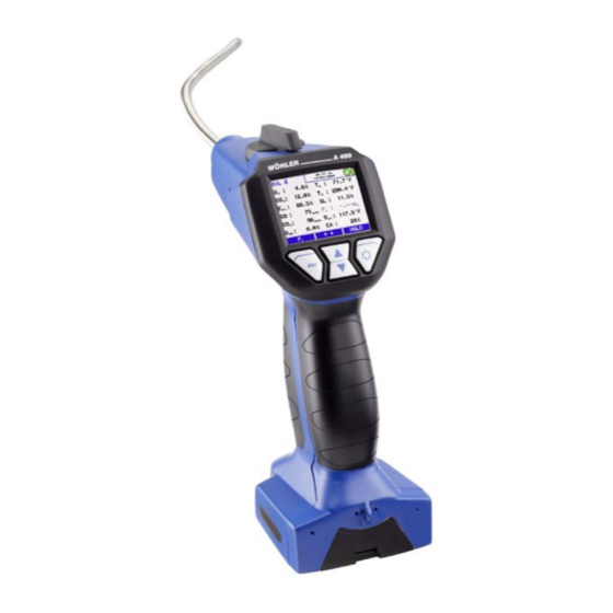
Page 10: Component Explanation
Component Explanation Component Explanation Figure 1: Overview Wohler A 400... - Page 11 Component Explanation Component Explanation Probe and hose assembly Color display Scroll and Zoom keys Enter and ON/OFF key ESC key IR printer interface Connection for ambient air temperature sensor Connection for charger Battery compartment 10 Connection for handloop 11 Connection for manifold pressure 12 Heatexchanger and watertrap control window 13 Filter cover...
-
Page 12: Models
Component Explanation Models The Wohler A 400 Flue Gas Analyzer is available in two different designs: • Wohler A 400, see figure 2 • Wohler A 400 , see figure 1 The probe and hose design makes the difference. The Wohler A 400... - Page 13 Component Explanation The stack gas is sampled through the probe into the base unit (see also page 36). The four step filter conditioning consists of: • The first step is the heat exchanger. Most of the water moister and particles will be removed from the sample.
-
Page 14: Display And Key Setup
Component Explanation Display and key setup The Wohler A 400 has a color 2.4' display (Figure 4). The OLED-technology allows reading the display from almost any angle of view. Four keys are available below the display to operate the Wohler A 400. -
Page 15: Getting Started
Getting started Getting started Check battery status Check the battery status. When the analyzer is switched on, the battery indication is displayed in the upper right hand corner of the screen. A fully charged set of batteries is shown as a solid green battery symbol (refer to chapter 5.1). - Page 16 Getting started ATTENTION! Ensure rechargeable batteries are equipped in the analyzer before charging. Never try to charge disposable batteries! Use 4 AA rechargeable or disposable batteries only. How to charge the batteries: • Before you plug the recharger into the outlet, connect it with the analyzer.
-
Page 17: Connect The Probe And Hose Assembly
Getting started Connect the probe and The Wohler A 400 comes with a replaceable probe and hose assembly, see Figure 7 and hose assembly (Wohler Figure 8. A 400 only) How to remove the probe and hose assembly: Unplug the thermocouple connector (Figure... -
Page 18: Manifold Pressure Connector
Figure 11: Display/Keys The Wohler A 400 provides a Zoom function for all combustion readings. Hold the up or down key pressed to zoom in or out. You can scroll the readings by clicking the up or down keys. -
Page 19: Turning The Analyzer On
Using the Analyzer ATTENTION! Do NOT place the analyzer unsecured, it can fall down and get damaged! During a combustion test either • hold the analyzer in one hand • place it with the magnetic holder to any appropriate surface. Turning the analyzer ON Hold the ON/OFF key pressed for about 3 seconds to turn ON the analyzer. -
Page 20: Performing A Combustion Efficency Test
Using the Analyzer Performing a Upon conclusion of self check and calibration procedure the analyzer will display the main combustion efficency combustion efficiency test screen. test You are ready to insert the probe into the stack and begin your test now. NOTE! Do NOT put the probe in an elbow. -
Page 21: Main Menu
Using the Analyzer When the analyzer is in 'HOLD' mode the Main menu following menu options are available: Figure 16: Main menu... -
Page 22: Option 'Tuning Guide
Using the Analyzer 5.4.1 Option 'TUNING GUIDE' The option 'TUNING GUIDE' offers an exceptional advanced guidance to the technician to properly adjust the burner. All combustion test related readings are presented in a graph over the excess air. The current reading is marked with a red box and any former reading is tracked with a green line. -
Page 23: Option 'Ambient Co
Using the Analyzer 5.4.2 Option 'AMBIENT CO' The option 'AMBIENT CO' offers a graphical assisted ambient CO test. The current ambient CO concentration is shown over the elapsed measurement time. Figure 19 shows an 'Ambient CO' test over a time period of 120 seconds and the current CO level is 7 ppm. -
Page 24: Option 'Print Record
• Option '↓↑' (center keys): click either up or down key to printout a full graphical report on your Wohler TD 600 thermal printer. To print a complete 'AMBIENT CO' test takes about 2 minutes. Figure 20: ambient CO test 'HOLD' •... -
Page 25: Option 'Fuel Selection
Using the Analyzer Make sure you point the electronic eyes of the analyzer, located in the handle, at the electronic eye of the printer during print out. If you desire multiple copies of the results click on 'PRINT' as above for an additional copy. Figure 22: Printing in progress 5.4.4 Option 'FUEL... - Page 26 Using the Analyzer The fuel customization screen allows you to change the specifications of any fuel. You can change the name of the User defined fuel only. Fuels are defined by: • Aggregate • (Oxygen reference level) 2ref • (maximum CO level) 2max •...
-
Page 27: Manifold Pressure
• Option '↓↑' (center keys): click either up or down key to print out a full graphical report on your Wohler TD 600 thermal printer. To print a complete ' MANIFOLD PRESSURE ' test takes about 2 minutes. •... -
Page 28: Option 'Save Record
Wohler TD 600 thermal printer. Figure 28: GRAPH mode screen The Wohler A 400 is capable of saving up to 100 5.4.7 Option 'SAVE RECORD' customer records. A customer record consist of •... -
Page 29: Option 'Pr Measurement
Using the Analyzer The lock symbol behind the 'SAVE RECORD' option indicates that the customer record is saved. Figure 30: SAVE RECORD, lock symbol 5.4.8 Option 'PR To enter the draft measurement the Analyzer offers two different options. The first one is MEASUREMENT' described in section 5.3 during a combustion test. -
Page 30: 5.4.10 Option 'Setup
Using the Analyzer 5.4.10 Option 'SETUP' Select the option 'SETUP' to enter the main setup menu. Use the keys to navigate through the menu. • Option 'Time' Change the current time of the analyzers internal clock. • Option 'Date' Change the current date of the analyzers internal calendar. - Page 31 Using the Analyzer When you are not using the Wohler TD 600 high speed thermal printer change this option to 'Other'. The Analyzer will then print out in a slow HP printer format. • Option 'Calculation' Change the combustion efficiency calculation between the North American US mode (ASME) or the European EN mode.
-
Page 32: 5.4.11 Option 'Calibration
'CALIBRATION' in the main menu. This option allows to digitally calibrate all sensors. NOTE! The calibration of the analyzer is allowed to trained personnel ONLY. Please contact Wohler for more information. Please refer to section 7.4.3. Turning OFF the To turn off the analyzer depress and hold the ON/OFF key. -
Page 33: Troubleshooting
Replace sensor or send sensor analyzer to Wohler certified service station 'Check filters!' Filters are wet or loaded Remove condensate and with particles replace all filters... -
Page 34: Maintenance
Maintenance Maintenance Proper operation of the Wohler A 400 requires regular maintenance. Maintenance work Interval Maintenance work After every combustion Remove condensate test and water from the condensate trap Replace cotton filter when wet or dirty Replace Water Stop filter when clogged... -
Page 35: Removal Of Condensate
7.3.2 LT-filter The gas way of the Wohler A 400 is designed for an extra long lifetime of the sensors. A special filter filled with LT-pellets is built into the gas way to extend sensor life. -
Page 36: Maintenance And Change Of Sensors
Maintenance Maintenance and change of sensors 7.4.1 Cleaning the gas way To clean the gas way follow the steps below: Turn OFF the Analyser. Remove black rubber filter cover. Pull water stop filter with cotton filter holder out. Pull off the cover of the cotton filter holder Replace cotton filter. -
Page 37: Sensor Diagnosis And Change
Maintenance 7.4.3 Sensor diagnosis and The Wohler A 400 has an advanced electronic self diagnosis program. To enter the diagnosis change screen click 'DIAG' during self check and calibration. The diagnosis screen shows: • Firmware version • Serial number •... - Page 38 Maintenance Figure 42: Change a sensor How to change a sensor: LT-filter Turn off the analyzer. Remove the batteries. Remove the two screws, see Figure 42, picture 1. Remove the sensor cover. CO (4000 ppm) Disconnect the sensor cable. -Sensor Pull the sensor out of the holder.
- Page 39 Maintenance 13. Turn on the analyzer. 14. Enter the calibration menu. 15. Enter Code '3318'. 16. Always change information for the replaced sensor the following way: • sensor: date and model. • CO sensor: date and calibration data. Figure 44: Access code entry Figure 45: O -sensor calibration Figure 46: CO-sensor calibration...
- Page 40 Maintenance 17. Exit calibration mode and confirm changes. 18. Run self check and calibration two times by turning the analyzer on and off. 19. Enter diagnostic menu and check status and data of the new sensor Figure 47: Confirm to save changes...
-
Page 41: Warranty And Service
Warranty and Service Warranty and Service Warranty Each Wohler A 400 Flue Gas Analyzer will be tested in all functions and will leave our factory only after extensive quality control testing. The final control will be recorded in detail in a test report and delivered with any unit. -
Page 42: Accessories
9152 Rubber ball p/n 2340 Spare parts 4 AA rechargeable batteries, 2 Ah p/n 9407 Water stop filter Wohler A 400, 3 pcs. p/n 9621 Cotton filter, short, 25 pcs. p/n 4286 Sensors Sensor A 400 field replaceable p/n 3354...
Need help?
Do you have a question about the A 400 and is the answer not in the manual?
Questions and answers