Panasonic PAN9026 Product Specification
Wi-fi dual band 2.4/5 ghz and bluetooth module
Hide thumbs
Also See for PAN9026:
- Developer's manual (27 pages) ,
- Quick start manual (30 pages) ,
- Quick start manual (34 pages)

Related Manuals for Panasonic PAN9026


Summary of Contents for Panasonic PAN9026
- Page 1 PAN9026 Wi-Fi Dual Band 2.4/5 GHz and Bluetooth Module Product Specification Rev. 0.1 Wireless Modules...
- Page 2 Coexistence interface for arbitration of co-located Overview WLAN, Bluetooth, or Mobile Wireless System (e.g. LTE) The PAN9026 is a 2.4/5 GHz ISM band Wi-Fi and • Bluetooth radio module which includes a wireless Generic interfaces include SDIO 3.0 and high-...
- Page 3 By purchase of any of the products described in this document the customer accepts the document's validity and declares their agreement and understanding of its contents and recommendations. Panasonic reserves the right to make changes as required at any time without notification. Please consult the most recently issued product specification before initiating or completing a design.
-
Page 4: Table Of Contents
PAN9026 Wi-Fi/BT Module Table of Contents About This Document ......................... 5 Purpose and Audience ......................5 Revision History ......................... 5 Use of Symbols ......................... 5 Related Documents ........................5 Product Overview ..........................6 Block Diagram ........................... 7 Pin Configurations ........................8 Power Management......................... -
Page 5: About This Document
This product specification provides details on the functional, operational, and electrical characteristics of the Panasonic PAN9026 modules. It is intended for hardware design, application, and OEM engineers. The product is referred to as “the PAN9026” or “the module” within this document. -
Page 6: Product Overview
2 Product Overview Wi-Fi and Bluetooth Radio Module The PAN9026 is a dual band 2.4/5 GHz 802.11 a/b/g/n Wi-Fi radio module with integrated Bluetooth BDR/EDR/LE, specifically designed for highly integrated and cost-effective applications. The simultaneous and independent operation of the two standards enables high data rates (802.11n) and low-power operation (Bluetooth Low Energy). -
Page 7: Block Diagram
PAN9026 Wi-Fi/BT Module 2 Product Overview 2.1 Block Diagram Product Specification Rev. 0.1 Page 7... -
Page 8: Pin Configurations
PAN9026 Wi-Fi/BT Module 2 Product Overview 2.2 Pin Configurations Pin Assignment Top View Ground plane keep out area 17,50 mm Pin Functions Pin Name Pin Type Description PCM_DOUT Output signal PCM data output signal General Purpose IO – GPIO[5]... - Page 9 PAN9026 Wi-Fi/BT Module 2 Product Overview Pin Name Pin Type Description PCM_DIN Input signal PCM data input signal General Purpose IO – GPIO[4] Digital I/O PCM_SYNC Input/Output PCM Sync Pulse signal, output if PCM master, input if PCM slave General Purpose IO –...
- Page 10 PAN9026 Wi-Fi/BT Module 2 Product Overview Pin Name Pin Type Description UART_SOUT Output Signal Serial data output to peripheral device General Purpose IO – GPIO[8] Digital I/O BT_FREQ Input Signal Information BT using channel which overlaps WLAN channel or not...
- Page 11 PAN9026 Wi-Fi/BT Module 2 Product Overview SDIO Pins Function Pin Name Pin Type Description 4-Bit Mode 1-Bit Mode SD_CLK Digital I/O Clock Clock SD_CMD Digital I/O Command Line Command Line SD_DAT0 Digital I/O Data Line bit [0] Data Line...
-
Page 12: Power Management
PAN9026 Wi-Fi/BT Module 2 Product Overview 2.3 Power Management 2.3.1 Power Configuration with 3.3V Host Operation 2.3.2 Power Configuration with 1.8V Host Operation PAN9026 VDD 1.8 V 1.8 V VIO/VIO SD 1.8 V 3.3 V 3.3 V VIO RF Step-up 3.3 V... -
Page 13: Host Interfaces
PAN9026 Wi-Fi/BT Module 2 Product Overview 2.4 Host Interfaces The bus interface connects several host interface bus units to the CPU bus of the device through the internal bus. The connection of each unit is multiplexed with other bus units. -
Page 14: Peripheral Bus Interface
PAN9026 Wi-Fi/BT Module 2 Product Overview 2.5 Peripheral Bus Interface The Peripheral Bus Unit (PBU) connects several low speed peripherals to the internal bus of the device. The device consists of the GPIO Interface and the One Time Programmable Memory. -
Page 15: Audio Interface
PAN9026 Wi-Fi/BT Module 2 Product Overview 2.6 Audio Interface The device supports a PCM and a proprietary TDM interface. Both interfaces are multiplexed on the same pins. Type Features • PCM Interface Master or slave mode • PCM bit width size of 8 bits or 16 bits •... -
Page 16: Coexistence
PAN9026 Wi-Fi/BT Module 2 Product Overview 2.7 Coexistence The implemented coexistence framework is based on the IEEE 802.15.2 recommended practice Packet Traffic Arbitration (PTA) scheme and the Bluetooth Special Interest Group (BTSIG) Core Specification Volume 7 (Wireless Coexistence Volume). - Page 17 PAN9026 Wi-Fi/BT Module 2 Product Overview 2.7.3 System Configuration External MWS Device RF Front End BCA BT Bluetooth BCA WLAN WLAN MWS to BCA COEX SIN External LTE Device COEX SOUT BCA to MWS 88W8977 Radio SoC Host External BCA Device...
- Page 18 PAN9026 Wi-Fi/BT Module 2 Product Overview 2.7.4 WCI-2 Interface The coexistence interface includes a Mobile Wireless System (MWS) transport controller to accommodate a 2-wire, UART-based serial transport interface. This interface is a standard full- duplex UART (TXD and RXD) carrying logical signals framed as UART characters. In addition, it allows support of multiple logical channels.
- Page 19 PAN9026 Wi-Fi/BT Module 2 Product Overview Real-Time Signaling Message The real-time signaling message is used to transport real-time signals over the 2-wire transport interface. The real-time signaling message conveys of the real-time signals (Volume 7, Part A) in one message.
- Page 20 PAN9026 Wi-Fi/BT Module 2 Product Overview Transport Control Message The transport control messages can modify the state and request state information of the MWS coexistence interface. Message MSG[0] MSG[1] MSG[2] MSG[3] MSG[4] Transport Control Message RESEND_REA L_TIME Signal Name...
- Page 21 PAN9026 Wi-Fi/BT Module 2 Product Overview MWS Inactivity Duration Message The inactivity duration messages is used to send the MWS_INACTIVITY_DURATION signal from the MWS device to the Coexistence Controller. Message MSG[0] MSG[1] MSG[2] MSG[3] MSG[4] MWS Inactivity Duration DURATION[0]...
- Page 22 PAN9026 Wi-Fi/BT Module 2 Product Overview 2.7.5 Bluetooth Coexistence Arbiter Type Features • Capability Programmable coexistence interface timing, interface modes, and signal polarity to support a variety of external Bluetooth devices • Programmable decision policies and transaction lock behavior for various use cases •...
- Page 23 PAN9026 Wi-Fi/BT Module 2 Product Overview Type Features Decision Policies System configuration is a major consideration when planning decision policies. The configuration governs how RF paths are shared and how much interference will occur. Interference combinations include: WLAN TX and Bluetooth TX ...
- Page 24 PAN9026 Wi-Fi/BT Module 2 Product Overview Type Features Transaction Stopping The arbiter allows control of what transfers can be stopped after an initial grant. If allowed, a transaction can be stopped for higher priority request. A transaction stop decision is a function of the decision policies and transaction stopping control.
- Page 25 PAN9026 Wi-Fi/BT Module 2 Product Overview 2.7.6 Bluetooth Capability Type Features Request Schemes The PTA signals are directly controlled by the hardware to meet timing requirements of the Bluetooth radio. The software controls the type of traffic in priority mode. Mechanism enforced for control include: •...
- Page 26 PAN9026 Wi-Fi/BT Module 2 Product Overview 2.7.7 WLAN Capability Type Features Capability The WLAN device technology uses an internal coexistence interface to exchange request/grant with the BCA. Features include: • Packet-based request signaling with direction and priority information •...
- Page 27 PAN9026 Wi-Fi/BT Module 2 Product Overview 2.7.8 LTE (MWS) Capability The device supports a BTSIG WCI-2 MWS coexistence signaling interface. The coexistence logical signaling is designed to enable a standard interface to allow an MWS device and a Coexistence Controller to exchange information and support cooperative coexistence.
- Page 28 PAN9026 Wi-Fi/BT Module 2 Product Overview 2.7.9 ZigBee (MWS) Coexistence Capability ZigBee is based on the IEEE 802.15.4 standard and it is used by a suite of communication protocols to create Personal Area Networks (PANs) supporting home automation, lighting control, etc.
-
Page 29: Wlan
PAN9026 Wi-Fi/BT Module 2 Product Overview 2.8 WLAN Type Features • IEEE 802.11/ 802.11 data rates 1 and 2 Mbps (DSSS) • 802.11b data rates 5.5 and 11 Mbps (CCK) Standards • 802.11a/g data rates 6, 9, 12, 18, 24, 36, 48, and 54 Mbps (OFDM) •... - Page 30 PAN9026 Wi-Fi/BT Module 2 Product Overview Type Features • WLAN Baseband 802.11n 1x1 SISO (WLAN SoC with SISO RF radio) • Backward compatibility with legacy 802.11a/b/g technology • WLAN/Bluetooth LNA sharing • PHY data rates up to 150 Mbps •...
- Page 31 PAN9026 Wi-Fi/BT Module 2 Product Overview Operation Modes Parameter Operation Mode Specification Standard Conformance IEEE 802.11/IEEE 802.11b IEEE 802.11a IEEE 802.11g IEEE 802.11n Modulation IEEE 802.11a OFDM IEEE 802.11b DSSS/CCK IEEE 802.11g OFDM IEEE 802.11n OFDM @ MCS0~7 and MCS32 (duplicate...
- Page 32 PAN9026 Wi-Fi/BT Module 2 Product Overview Supported Channels and Frequencies 2.4 GHz – IEEE 802.11b/g/n 20 MHz Channels 40 MHz Channels Channel Frequency Unit Channel Frequency Unit 2 412 2 422 2 417 2 427 2 422 2 432...
- Page 33 PAN9026 Wi-Fi/BT Module 2 Product Overview 5 GHz – IEEE 802.11a/n 20 MHz Channels 40 MHz Channels Channel Frequency Unit Channel Frequency Unit 5 745 149-153 5 755 5 765 157-161 5 795 5 785 5 805 5 825 5 GHz –...
-
Page 34: Bluetooth
PAN9026 Wi-Fi/BT Module 2 Product Overview 2.9 Bluetooth Type Features • General Supports Bluetooth 4.2 • Shared Tx/Rx path for Bluetooth • Digital Audio Interface including PCM/TDM interface for voice application • Bluetooth and WLAN coexistence • WLAN/Bluetooth Coexistence (BCA) protocol support •... - Page 35 PAN9026 Wi-Fi/BT Module 2 Product Overview Type Features • Bluetooth Low Energy Advertiser, Scanner, Initiator, Master, and Slave roles support (connects up to 16 links) (LE) • Shared RF with BR/EDR • Encryption AES support • Hardware support for intelligent Adaptive Frequency Hopping (AFH) •...
-
Page 36: Detailed Description
PAN9026 Wi-Fi/BT Module 3 Detailed Description 3 Detailed Description 3.1 Dimensions All dimensions are in millimeters. Item Dimension Tolerance Remark 1 Width 10.00 ± 0.35 2 Length 17.50 ± 0.35 3 Height 2.55 ± 0.20 with case Product Specification Rev. 0.1... -
Page 37: Footprint
PAN9026 Wi-Fi/BT Module 3 Detailed Description 3.2 Footprint The outer dimensions have a tolerance of 0.35 mm. Top View 8,80 mm 6,00 mm 2,20 mm 2,20 mm 0,80 mm Ground plane keep out area 0,80 mm 4,80 mm... -
Page 38: Packaging
PAN9026 Wi-Fi/BT Module 3 Detailed Description 3.3 Packaging The product is a mass production status product and will be delivered in the package described below. 3.3.1 Tape Dimensions 0.30± 0.03 2.0± 0.15(I) + 0.1 4.0± 0.15(II) 1.75± 0.1 2.0MIN SECTION Y-Y R0.75... - Page 39 PAN9026 Wi-Fi/BT Module 3 Detailed Description 3.3.2 Packing in Tape Empty spaces in the component packed area shall be less than two per reel and those spaces shall not be consecutive. The top cover tape shall not be found on reel holes and it shall not stick out from the reel.
- Page 40 PAN9026 Wi-Fi/BT Module 3 Detailed Description 3.3.4 Reel Dimension Product Specification Rev. 0.1 Page 40...
- Page 41 PAN9026 Wi-Fi/BT Module 3 Detailed Description 3.3.5 Package Label Example (1T) Lot code (1P) Customer order number, if applicable (2P) Order number (9D) Date code Quantity (HW/SW) Hardware/Software version Product Specification Rev. 0.1 Page 41...
- Page 42 PAN9026 Wi-Fi/BT Module 3 Detailed Description 3.3.6 Total Package moisture-sensitive print (already exist on barrier bag) barcode label barrier bag sealed desiccant 1) 2) moisture indicator 1) quantity of desiccant according to calculation barcode 2) optional: desiccant placed into...
-
Page 43: Case Marking
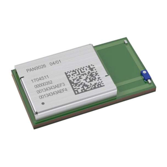
PAN9026 Wi-Fi/BT Module 3 Detailed Description 3.4 Case Marking Example for PAN9026 PAN9026 HW/SW ES M/N: ENWF9201A1EF YYWWDLL 12345678 0013430B801E 0013430B801F Top View Brand name Hardware/Software version Engineering Sample (optional) Model Name/ENW number Lot code Serial number WLAN MAC address... -
Page 44: Specification
PAN9026 Wi-Fi/BT Module 4 Specification 4 Specification All specifications are over temperature and process, unless indicated otherwise. 4.1 Default Test Conditions Temperature: 25 ± 10 °C Humidity: 40 to 85 % RH Supply Voltage: VDD2V2 = 2.2 V VDD1V8 = 1.8 V... -
Page 45: Absolute Maximum Ratings
PAN9026 Wi-Fi/BT Module 4 Specification 4.2 Absolute Maximum Ratings The maximum ratings may not be exceeded under any circumstances, not even momentarily or individually, as permanent damage to the module may result. Symbol Parameter Condition Min. Typ. Max. Units... -
Page 46: Recommended Operating Conditions
PAN9026 Wi-Fi/BT Module 4 Specification 4.3 Recommended Operating Conditions The maximum ratings may not be exceeded under any circumstances, not even momentarily or individually, as permanent damage to the module may result. Symbol Parameter Condition Min. Typ. Max. Units... - Page 47 PAN9026 Wi-Fi/BT Module 4 Specification 4.3.1 Digital Pin Characteristics VIO with 1.8 V Operation Symbol Parameter Condition Min. Typ. Max. Units High level input 1.8 V operation (V = 1.8 V) 0.7 V + 0.4 voltage Low level input 1.8 V operation (V...
- Page 48 PAN9026 Wi-Fi/BT Module 4 Specification VIOSD 3.3 V Operation for SDIO I/F Symbol Parameter Condition Min. Typ. Max. Units High level input 3.3 V operation (V = 3.3 V) 0.7 V IOSD IO_SD IO_SD voltage +0.4 Low level input 3.3 V operation (V...
- Page 49 PAN9026 Wi-Fi/BT Module 4 Specification 4.3.2 Current Consumption The current consumption depends on the user scenario, the setup and timing of the power modes. Assume V = 2.2 V, V = 1.8 V, V = 3.3 V, V = 3.3 V, V = 3.3 V...
- Page 50 PAN9026 Wi-Fi/BT Module 4 Specification Symbol Parameter Condition Min. Typ. Max. Units Active 5 GHz band 802.11a @ 6 Mbps VDD1V8 @ RX Receive 5 GHz band 802.11n 20M @ 72 Mbps 2.4 GHz band 802.11b @ 11 Mbps 2.4 GHz band 802.11g @ 54 Mbps...
- Page 51 PAN9026 Wi-Fi/BT Module 4 Specification 4.3.3 Internal Operating Frequencies Symbol Parameter Condition Min. Typ. Max. Units Refers to clock speed of SoC’s CPU1/System SYSCLK1 /Encryption CPU1 clock speed Refers to clock speed of SoC’s CPU2 SYSCLK2 CPU2 Crystal Frequency tolerance < ±10 ppm...
- Page 52 PAN9026 Wi-Fi/BT Module 4 Specification 4.3.4 Power-up Sequence VIOSD VIORF VDD2V2 VDD1V8 Symbol Parameter Min. Typ. Max. Units Voltage level of V DD1V8 DD2V2 Voltage level of V DD2V2 Product Specification Rev. 0.1 Page 52...
- Page 53 PAN9026 Wi-Fi/BT Module 4 Specification 4.3.5 Host Interface 4.3.5.1 SDIO Interface The SDIO Interface pins are powered from the VIOSD voltage supply with either 3.3 V or 1.8 V. The SDIO electrical specifications are identical for the 1-bit and 4-bit SDIO modes.
- Page 54 PAN9026 Wi-Fi/BT Module 4 Specification SDIO Protocol Timing Diagram – Default Speed Mode (VIOSD 3.3 V) SDIO Protocol Timing Diagram – High-Speed Mode (VIOSD 3.3 V) Product Specification Rev. 0.1 Page 54...
- Page 55 PAN9026 Wi-Fi/BT Module 4 Specification SDIO Timing Data – SDR12, SDR25, SDR50 Modes (VIOSD 1.8 V) Symbol Parameter Condition Min. Typ. Max. Units Clock frequency SDR12/SDR25/SD Input setup time SDR12/SDR25/SD SDR12/SDR25/SD Input hold time Clock time SDR12/SDR25/SD Rise time, fall time SDR12/SDR25/SD 0.2 *...
- Page 56 PAN9026 Wi-Fi/BT Module 4 Specification SDIO Timing Data – DDR50 Mode (VIOSD 1.8V) Symbol Parameter Condition Min. Typ. Max. Units Clock Clock time DDR50 50 MHz (max) between rising edges Rise time, fall time DDR50 0.2 * < 4.00 ns (max)
- Page 57 PAN9026 Wi-Fi/BT Module 4 Specification SDIO CMD Timing Diagram – DDR50 Mode (VIOSD 1.8 V, 50 MHz) SDIO DAT[3:0] Timing Diagram – DDR50 Mode (VIOSD 1.8 V, 50 MHz) In DDR50 mode, DAT[3:0] lines are sampled on both edges of the clock (not applicable for CMD line).
- Page 58 PAN9026 Wi-Fi/BT Module 4 Specification 4.3.5.2 High-Speed UART Interface The High-Speed UART Interface pins are powered from the VIO voltage supply with either 3.3 V or 1.8 V. 4.3.1 Digital Pin Characteristics DC specification The UART interface operation includes: •...
- Page 59 PAN9026 Wi-Fi/BT Module 4 Specification Interface Transport Settings Item Range Default Comment Baudrate 1 200 ~ 4 000 000 3 000 000 Baud Data Bits 5 ~ 8 LSB first Parity Bits 0 ~ 4 Stop Bit 1/1.5/2 Supported Baud Rates...
- Page 60 PAN9026 Wi-Fi/BT Module 4 Specification 4.3.6 Peripheral Interface The Peripheral Interface pins are powered from the voltage supply VIO with either 3.3 V or 1.8 V. 4.3.1 Digital Pin Characteristics DC specification 4.3.6.1 GPIO Interface The General-Purpose I/O (GPIO) interface is used to implement user-defined input and output signals to and from the device, such as external interrupts and other user-defined I/Os.
- Page 61 PAN9026 Wi-Fi/BT Module 4 Specification 4.3.7 Audio Interface ® The interface supports a PCM and a Marvell proprietary TDM interface. Both interfaces are muxed on the same pins. 4.3.7.1 PCM Interface Interface Signals Pin No Signal Name Specification Type...
- Page 62 PAN9026 Wi-Fi/BT Module 4 Specification PCM Timing Data – Master Mode Symbol Min. Typ. Max. Units 2/2.048 BCLK Duty Cycle BCLK BCLK rise/fall DISU DIHO PCM Timing Diagram – Master Mode BCLK DOUT DIHO DISU SYNC Product Specification Rev. 0.1...
- Page 63 PAN9026 Wi-Fi/BT Module 4 Specification PCM Timing Data – Slave Mode Symbol Min. Typ. Max. Units 2/2.048 BCLK Duty Cycle BCLK BCLK rise/fall DISU DIHO BFSU BFHO PCM Timing Diagram – Slave Mode BCLK DOUT DISU DIHO BFSU BFHO SYNC Product Specification Rev.
- Page 64 PAN9026 Wi-Fi/BT Module 4 Specification 4.3.7.2 TDM Interface Interface Signals Module Signal Name Specification Type Description Pin No Name A1 PCM_DOUT DOUT Output Serial data output B1 PCM_CLK BCLK Input TDM bit clock signal B2 PCM_DIN Input Serial data input...
- Page 65 PAN9026 Wi-Fi/BT Module 4 Specification 4.3.8 Coexistence Interface The Coexistence Interface pins are powered from the voltage supply VIO with either 3.3 V or 1.8 V. 4.3.1 Digital Pin Characteristics DC specification Product Specification Rev. 0.1 Page 65...
-
Page 66: Rf Electrical Characteristics
PAN9026 Wi-Fi/BT Module 4 Specification 4.4 RF Electrical Characteristics 4.4.1 WLAN Radio Specification Receive Mode Parameter Condition Min. Typ. Max. Units 2.4 GHz – IEEE 802.11b/g/n RF frequency range 2 400 2 483.5 5 GHz – IEEE 802.11a/n 4 900... - Page 67 PAN9026 Wi-Fi/BT Module 4 Specification 4.4.2 WLAN RF Characteristics 4.4.2.1 RF Characteristics for IEEE 802.11b Assume V = 2.2 V, V = 1.8 V, V = 3.3 V, V = 3.3 V, V = 3.3 V DD2V2 DD1V8 IORF...
- Page 68 PAN9026 Wi-Fi/BT Module 4 Specification 4.4.2.2 RF Characteristics for IEEE 802.11g Assume V = 2.2 V, V = 1.8 V, V = 3.3 V, V = 3.3 V, V = 3.3 V DD2V2 DD1V8 IORF IOSD and T = 25 °C, if nothing else stated.
- Page 69 PAN9026 Wi-Fi/BT Module 4 Specification 4.4.2.3 RF Characteristics for IEEE 802.11n (BW 20 MHz, 2.4 GHz) Assume V = 2.2 V, V = 1.8 V, V = 3.3 V, V = 3.3 V, V = 3.3 V DD2V2 DD1V8...
- Page 70 PAN9026 Wi-Fi/BT Module 4 Specification 4.4.2.4 RF Characteristics for IEEE 802.11n (BW 40 MHz, 2.4 GHz) Assume V = 2.2 V, V = 1.8 V, V = 3.3 V, V = 3.3 V, V = 3.3 V DD2V2 DD1V8...
- Page 71 PAN9026 Wi-Fi/BT Module 4 Specification 4.4.2.5 RF Characteristics for IEEE 802.11n (BW 20 MHz, 5 GHz) Assume V = 2.2 V, V = 1.8 V, V = 3.3 V, V = 3.3 V, DD2V2 DD1V8 IORF IOSD = 3.3 V, and T = 25 °C, if nothing else stated.
- Page 72 PAN9026 Wi-Fi/BT Module 4 Specification 4.4.2.6 RF Characteristics for IEEE 802.11n (BW 40 MHz, 5 GHz) Assume V = 2.2 V, V = 1.8 V, V = 3.3 V, V = 3.3 V, DD2V2 DD1V8 IORF IOSD = 3.3 V, and T = 25 °C, if nothing else stated.
- Page 73 PAN9026 Wi-Fi/BT Module 4 Specification 4.4.2.7 RF Characteristics for IEEE 802.11a Assume V = 2.2 V, V = 1.8 V, V = 3.3 V, V = 3.3 V, DD2V2 DD1V8 IORF IOSD = 3.3 V, and T = 25 °C, if nothing else stated.
- Page 74 PAN9026 Wi-Fi/BT Module 4 Specification 4.4.3 Bluetooth RF Characteristics Assume V = 2.2 V, V = 1.8 V, V = 3.3 V, V = 3.3 V, DD2V2 DD1V8 IORF IOSD = 3.3 V, and T = 25 °C, if nothing else stated.
- Page 75 PAN9026 Wi-Fi/BT Module 4 Specification 4.4.3.2 Transmitter Section RF Characteristics Parameter Condition Min. Typ. Max. Units RF frequency range 2 400 2 483.5 Maximum Output power Basic Rate (BR) Enhanced Data Rate (EDR) Low Energy (LE) Gain range Gain control...
-
Page 76: Reliability Tests
PAN9026 Wi-Fi/BT Module 4 Specification 4.5 Reliability Tests The measurement should be done after the test device has been exposed to room temperature and humidity for one hour. Item Limit Condition • 1 Vibration test Electrical parameter should be in Freq.: 10~50 Hz;... -
Page 77: Recommended Soldering Profile
PAN9026 Wi-Fi/BT Module 4 Specification 4.6 Recommended Soldering Profile • Reflow permissible cycle: 2 • Opposite side reflow is prohibited due to module weight • More than 75 percent of the soldering area shall be coated by solder •... -
Page 78: Cautions, Life Support Policy, Rohs Declaration, And Regulatory Information
PAN9026 Wi-Fi/BT Module 5 Cautions, Life Support Policy, RoHS Declaration, and Regulatory Information 5 Cautions, Life Support Policy, RoHS Declaration, and Regulatory Information 5.1 Cautions Failure to follow the guidelines set forth in this document may result in degrading of the product’s functions and damage to the product. - Page 79 PAN9026 Wi-Fi/BT Module 5 Cautions, Life Support Policy, RoHS Declaration, and Regulatory Information 5.1.3 Usage Condition Notes 1. Take measures to protect the unit against static electricity. If pulses or other transient loads (a large load applied in a short time) are applied to the products, check and evaluate their operation befor assembly on the final products.
- Page 80 7. When you have any question or uncertainty, contact Panasonic. Product Specification Rev. 0.1 Page 80...
-
Page 81: Life Support Policy
5 Cautions, Life Support Policy, RoHS Declaration, and Regulatory Information 5.2 Life Support Policy This Panasonic Industrial Devices Europe GmbH product is not designed for use in life support appliances, devices, or systems where malfunction can reasonably be expected to result in a... -
Page 82: Appendix
PAN9026 Wi-Fi/BT Module 6 Appendix 6 Appendix 6.1 Ordering Information Variants and Versions Order Number Brand Name Description ENWF9201A1EF PAN9026 Wif-Fi/Bluetooth radio module IEEE 802.11 a/b/g/n 1 000 BT/BLE 4.2 with a ceramic chip-antenna 6.2.2 Product For further information please refer to our product documentation Information. -
Page 83: Contact Details
For Panasonic Sales assistance in the EU, visit https://eu.industrial.panasonic.com/about-us/contact-us Email: wireless@eu.panasonic.com For Panasonic Sales assistance in North America, visit the Panasonic Sales & Support Tool to find assistance near you at https://na.industrial.panasonic.com/distributors Please visit the Panasonic Wireless Technical Forum to submit a question at https://forum.na.industrial.panasonic.com...
Need help?
Do you have a question about the PAN9026 and is the answer not in the manual?
Questions and answers