
Related Manuals for Panasonic PAN1740A


Summary of Contents for Panasonic PAN1740A
- Page 1 PAN1740A ® Bluetooth Low Energy Module Module Integration Guide Rev. 1.1 Wireless Connectivity...
- Page 2 PAN1740A Bluetooth Module 1 About This Document Overview Features • The PAN1740A is an optimized version of the Pre-programmed Bluetooth/MAC address • PAN1740, offering a reduced boot time and Includes 16 MHz and 32 768 kHz crystal supporting up to eight connections. It has a fully calibrated up to 1 ppm •...
- Page 3 Panasonic Industrial Devices Europe GmbH (Panasonic) reserves the right to make changes as required at any time without notification. Please consult the most recently issued Module Integration Guide before initiating or completing a design.
- Page 4 To the maximum extent allowable by Law Panasonic assumes no liability whatsoever including without limitation, indirect, consequential, special, or incidental damages or loss, including without limitation loss of profits, loss of opportunities, business interruption, and loss of data.
-
Page 5: Table Of Contents
Getting Started ........................... 16 Device Drivers ........................16 Software Examples ......................16 Run the Keil Project (Example) ....................17 Proximity Profile with two PAN1740A USB-Dongles (Example) ..........20 Smart Snippets ........................... 23 Program Structure ......................23 Application Demo: Proximity Profile ..................27 Dialog Serial Port Service (DSPS) .................... -
Page 6: About This Document
This guide gives an overview about the hardware design requirements by providing a reference design, which is the evaluation board of the PAN1740A. It describes how to use the PAN1740A ®... -
Page 7: Related Documents
The message Failed to save your data is displayed. Enter the value Product 123. Indicates a key on the keyboard, e.g. F10 . 1.4 Related Documents 13.2 Product For related documents please refer to the Panasonic website Information. Module Integration Guide Rev. 1.1 Page 7 of 44... -
Page 8: Overview
2 Overview 2 Overview The PAN1740A is an optimized version of the PAN1740, offering a reduced boot time and supporting up to eight connections. It has a fully integrated radio transceiver and baseband processor for Bluetooth 5 LE. It can be used as a stand-alone application processor or as a data pump in hosted systems. -
Page 9: Pan1740A Module
PAN1740A Bluetooth Module 3 PAN1740A Module 3 PAN1740A Module 3.1 Block Diagram Total capacity shall not exceed 2.5 µF. The total inductance shall not exceed 2.5 µH. There is no resistor value in this design. Module Integration Guide Rev. 1.1 Page 9 of 44... -
Page 10: Footprint
PAN1740A Bluetooth Module 3 PAN1740A Module 3.2 Footprint The dimensions are in millimeters. The outer dimensions have a tolerance of ±0.2 mm. The inner pins (2, 4, 6, 9, 11, 14, 16, 18, 21, 23) are shifted to the center by 1 mm. -
Page 11: Placement
Keep this product away from other high frequency circuits. The antenna requires a cutout area of 5 mm x 3 mm under the PAN1740A module. This “Keep out Area” shall be located in every layer under the module antenna. Note for example the “Keep out Area”... - Page 12 PAN1740A Bluetooth Module 3 PAN1740A Module All dimensions are in millimeters. Use a ground plane in the area surrounding the module wherever possible. It is recommended to place the module: • In the center (horizontal) of mother PCB. •...
-
Page 13: Reference Design
PAN1740A Bluetooth Module 4 Reference Design 4 Reference Design 4.1 USB-Dongle 4.1.1 Functionality • Atmel µC includes Segger USB-to-UART programmer (serial number on the backside) • OTP cannot be damaged (fail-safe development) • ® Runs with Dialog’s Keil Compiler projects •... -
Page 14: Mother Board
PAN1740A Bluetooth Module 4 Reference Design 4.2 Mother Board 4.2.1 Functionality • Can be used with PAN1740A Adapter Board • OTP can be programmed • Runs with Dialog’s Keil Compiler projects • Runs with Connection Manager • Can be used for software development "on the fly"... -
Page 15: Adapter Board
PAN1740A Bluetooth Module 4 Reference Design 4.3 Adapter Board Schematic J1_A J1_B MOD1 PAN1740 P0.0 VPP 14 P0.0 P0.1 SWCLK SW_CLK 16 P0.1 P0.2 SWDIO SW_DIO 18 P0.2 P0.0 P0.3 P0.3 P0.2 P0.1 P0.4 VCC 8 P0.4 P0.3 P0.5 P0.5... -
Page 16: Getting Started
For further information please visit https://www.segger.com/downloads/jlink/. 5.2 Software Examples The PAN1740A USB evaluation board is delivered without any preinstalled software examples, but the following chapters describe how to use the recommended development environment and the Dialog Semiconductors Software Development Kit (SDK) to run different kinds of software examples. -
Page 17: Run The Keil Project (Example)
PAN1740A Bluetooth Module 6 Run the Keil Project (Example) 6 Run the Keil Project (Example) The following requirements must be met: SDK is installed. USB-Dongle is installed. Use always the latest release from Dialog’s website https://www.dialogs.com/. 1. Open the Dialog SDK. - Page 18 PAN1740A Bluetooth Module 6 Run the Keil Project (Example) 4. Configure the Flash Target: Flash > Configure Flash Tools. Choose Settings. 5. Click on the tab Debug (1). 6. Setup the Port to SW (2). 7. Click OK (3).
- Page 19 PAN1740A Bluetooth Module 6 Run the Keil Project (Example) 8. Click on the icon Build to build the target files. 9. Click on the icon Debug to run the debug session. The proximity project has now been compiled and downloaded into the RAM of the PAN1740A ETU.
-
Page 20: Proximity Profile With Two Pan1740A Usb-Dongles (Example)
PAN1740A Bluetooth Module 7 Proximity Profile with two PAN1740A USB-Dongles (Example) 7 Proximity Profile with two PAN1740A USB-Dongles (Example) This example uses Dialog’s SDK version 3.0.2.1. The following requirement must be met: ® Microsoft Visual C++ 2010 Express – Freeware Compiler is installed. - Page 21 PAN1740A Bluetooth Module 7 Proximity Profile with two PAN1740A USB-Dongles (Example) The Debug session must be stopped. 1. Open the folder Monitor Host Application in the SDK. 2. Open the project file host_proxm.sln with the Microsoft C++ Compiler. 3. Compile and run the software.
- Page 22 PAN1740A Bluetooth Module 7 Proximity Profile with two PAN1740A USB-Dongles (Example) 7. Determine the correct COM port using Windows Device Manager and enter this port number in the proximity host application (DOS window). The receiver side will show the connection status.
-
Page 23: Smart Snippets
8 Smart Snippets 8 Smart Snippets The following description describes the structure and the usage of Smart Snippets in a nutshell. For more information as well as related documents, please refer to the Panasonic website 13.2 Product Information. 8.1 Program Structure For details, please refer to the Smart Snippets help (Help/User Guide/Sleep Mode Advisor). - Page 24 PAN1740A Bluetooth Module 8 Smart Snippets 8.1.2 Board Setup The tab Board Setup in the toolbox has to be used before any other tool as it establishes a communication with the development kit during the boot sequence and comes along with two lists.
- Page 25 PAN1740A Bluetooth Module 8 Smart Snippets 8.1.4 Power Profiler The tool Power Profiler enables the user to measure the power consumption of the desired application with all its functionality. Start the measurement 1. Click Initialize. The program will be initialized and the COM port connection will be opened.
- Page 26 PAN1740A Bluetooth Module 8 Smart Snippets Toolbar The toolbar can be found in the top of Smart Snippets and enables the user to add: • Measurements and markers • Export/import data to/from CSV-files • Clear secondary current data •...
-
Page 27: Application Demo: Proximity Profile
8.2 Application Demo: Proximity Profile This application example demonstrates the usage of Smart Snippets based on the previously used proximity profile demo. Two evaluation boards “DA14580” with PAN1740A adapter boards are used which are connected to Smart Snippets. One kit is loaded with the application code for the monitor monitor_fe_usb_full_emb_sys- ram.hex by the UART Booter. - Page 28 PAN1740A Bluetooth Module 8 Smart Snippets Once the devices are connected, Smart Snippets enables live evaluation of the application code for instance by measuring the power consumption as depicted below. Module Integration Guide Rev. 1.1 Page 28 of 44...
-
Page 29: Dialog Serial Port Service (Dsps)
9.1 Pro Kit with PAN1740A Adapter Board (iPod) The following example shows an easy application of the SPS with Dialog’s Pro Kit with a PAN1740A Adapter Board as device and an iPod running the DSPS application as host to exchange data. - Page 30 PAN1740A Bluetooth Module 9 Dialog Serial Port Service (DSPS) This pin assignment can be changed to any desired pin assignment in the application source code file periph_setup.h. To simplify the connection by using jumpers, the following pin assignment is suitable.
- Page 31 PAN1740A Bluetooth Module 9 Dialog Serial Port Service (DSPS) The following window appears. Tab Description The tab Console enables to send data (ASCII or HEX) immediately after typing the data into the field Send Console Mode Data and receives data from the device, e.g. Smart Snippet UART Terminal, as shown below.
-
Page 32: Two Pro Kits With Pan1740A Adapter Board
9.2 Two Pro Kits with PAN1740A Adapter Board Similar to the previous example it is possible to use two of Dialog’s Pro Kits with PAN1740A Adapter Boards to emulate a serial port. - Page 33 PAN1740A Bluetooth Module 9 Dialog Serial Port Service (DSPS) 2. Disable the sleep mode, as this is not fully supported for software flow control. 3. Compile the amended source codes. 4. Download the output .hex-files onto the sticks by using Dialog’s Connection Manager or ®...
-
Page 34: Production Tools
PAN1740A Bluetooth Module 10 Production Tools 10 Production Tools To program the PAN1740A in production a J-Link programmer and the 6.8 V programming voltage on the input pin VPP is required. Example schematic for a programming jig: IC2G$2 SC14580 JTAG SEGGER JLinkARM... -
Page 35: Regulatory And Certification Information
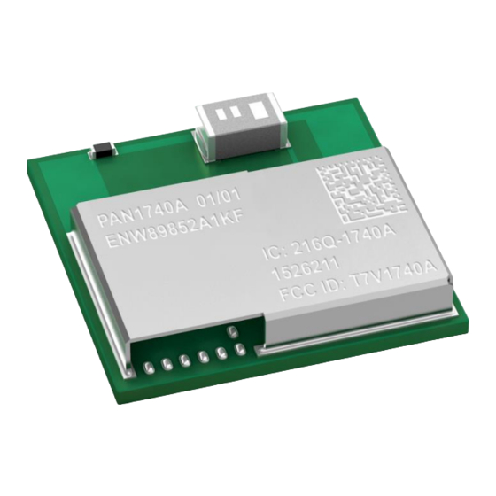
The FCC requires the user to be notified that any changes or modifications made to this device that are not expressly approved by Panasonic Industrial Devices Europe GmbH may void the user's authority to operate the equipment. This equipment has been tested and found to comply with the limits for a Class B digital device, pursuant to Part 15 of the FCC Rules. - Page 36 The end product must in any case be labelled on the exterior with: "Contains FCC ID: T7V1740A " Due to the PAN1740A model size, the FCC identifier is displayed in the installation instruction only and it cannot be displayed readable on the module’s label due to the limited size.
-
Page 37: Innovation, Science, And Economic Development (Ised) For Canada
Any notification to the end user of installation or removal instructions about the integrated radio module is not allowed. The radiated output power of the PAN1740A with a mounted ceramic antenna (FCC ID: T7V1740A) is below the FCC radio frequency exposure limits. - Page 38 The end customer has to assure that the device has a distance of more than 5 mm from the human body under all circumstances. If the end customer application intends to use the PAN1740A in a distance smaller 5 mm from the human body, SAR evaluation has to be repeated by the OEM.
- Page 39 The following IC notice has to be printed in English and French in the OEM end product user information: English The device PAN1740A, including the integrated antenna mentioned in 11.2.5 Approved Antenna List, complies with Canada RSS-GEN Rules. The device meets the requirements for modular transmitter approval as detailed in RSS-Gen.
- Page 40 Panasonic IC identifier for this product as well as the IC Notice above. The IC identifier is: IC: 216Q-1740A This IC identifier is valid for the PAN1740A module. In any case, the end product must be labelled on the exterior with: "Contains IC: 216Q-1740A”...
-
Page 41: European Conformity According To Red (2014/53/Eu)
The end customer equipment must meet the actual Safety/Health requirements according to RED. PAN1740A and its model versions in the specified reference design can be used in all countries of the European Economic Area (Member States of the EU, European Free Trade Association States [Iceland, Liechtenstein, Norway]), Monaco, San Marino, Andorra, and Turkey. -
Page 42: Bluetooth
For Bluetooth end products which integrate the PAN1740A the OEM needs to apply for an own end product listing (EPL) at the Bluetooth SIG. If the PAN1740A is used on more than one OEM product, costs can be saved by applying for a family EPL. -
Page 43: Restricted Use
Panasonic customers using or selling these products for use in such applications do so at their own risk and agree to fully indemnify Panasonic Industrial Devices Europe GmbH for any damages resulting. -
Page 44: Contact Details
PAN1740A Bluetooth Module 13 Contact Details 13 Contact Details 13.1 Contact Us Please contact your local Panasonic Sales office for details on additional product options and services: For Panasonic Sales assistance in the EU, visit https://eu.industrial.panasonic.com/about-us/contact-us Email: wireless@eu.panasonic.com For Panasonic Sales assistance in North America, visit the Panasonic website “Sales &...
Need help?
Do you have a question about the PAN1740A and is the answer not in the manual?
Questions and answers