Table of Contents

Subscribe to Our Youtube Channel
Related Manuals for Viconics VC3000 Series


Summary of Contents for Viconics VC3000 Series
-
Page 1: Table Of Contents
VC3000 Series Line Voltage Switching Relay Pack Controllers Installation Guide Commercial and Hotel/Lodging HVAC Fan Coil Applications CONTENTS Disclaimers Important Symbols Installation Communication Wiring To VTRX3XXA Terminal Equipment Controller Wiring of Remote Inputs to VC3504E and VC3404E VC3xxxE LED Operation Model Chart Terminals, Wire Identification &... -
Page 2: Disclaimers
Installation Guide VC3000 Series DISCLAIMERS • The VTR8000 series controller is only to be used in conjuction with the VC3000 line voltage switching relay pack. Together they are used as operating controls for high voltage fan coil units. • If replacing an existing Line Voltage FCU Controller, label the wires before removal of the controller. -
Page 3: Installation
Installation Guide VC3000 Series INSTALLATION All wiring must conform to the regulations of local and national electrical codes. Please read the following instructions carefully before proceeding with the installation. Failure to follow the instructions could damage the product or cause a hazardous condition. Installation must be performed by a qualified service technician or electrician. -
Page 4: Communication Wiring To Vtrx3Xxa Terminal Equipment Controller
Proper Installation and Use VC3000 series transformer relay packs are to be used only as operating controls. If installed incorrectly the intended application may fail or lead to personal injury or loss of property. It is the responsibility of the end user to ensure that the device has been properly installed by a certified professional and that proper safety precautions have been taken to protect against failures. -
Page 5: Wiring Of Remote Inputs To Vc3504E And Vc3404E
Installation Guide VC3000 Series Possible Network Wiring Topology The VTR83xxA to VC3000 transformer relay pack can use any network wiring topology as required or based on topology of existing wires. VC3XXXE LED OPERATION LED Status Cause Solution No communication between the VTRX3xxA and the VC3xxxE... -
Page 6: Model Chart
Installation Guide VC3000 Series MODEL CHART VC3300E5000 VC3514E5000 Part # VC3500E5000 VC3504E50400 VC3400E5000 VC3404E5000 Slave Fan Occ. Output Unit 2 pipes 2 pipes 2 pipes 2 pipes 2 pipes 2 pipes with 2 pipes with 2 pipes with 2 pipes with... -
Page 7: Terminals, Wire Identification & Ratings
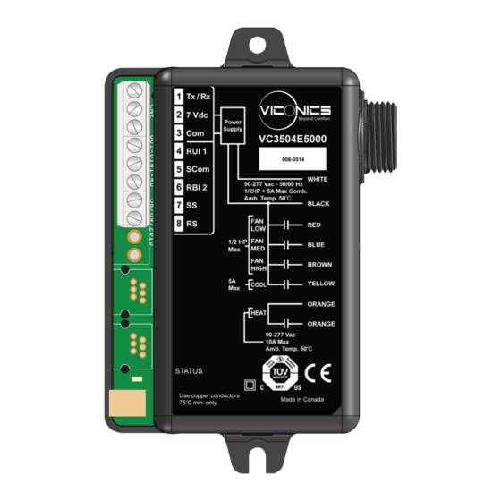
Installation Guide VC3000 Series TERMINALS, WIRE IDENTIFICATION & RATINGS VC3514E5000 VC3300E5000 Part # VC3500E5000 VC3504E5000 Occupancy VC3400E5000 VC3404E5000 Slave Fan Output Unit Low Voltage Low voltage Low voltage Low voltage No local inputs No local inputs No local inputs Terminals... -
Page 8: Typical Wiring Example Dimensions
Installation Guide VC3000 Series TYPICAL WIRING EXAMPLE DIMENSIONS SPECIFICATIONS Power Supply 90 to 277 VAC universal, 50-60 Hz Heat Valve: (Orange wires): 10 Amps @ 277 VAC maximum Output ratings Cool Valve: (Yellow wire): 5 Amps @ 277 VAC maximum... -
Page 9: Dimensions
VC3000 Series DIMENSIONS IMPORTANT NOTICE VC3000 series transformer relay packs are to be used only as operating controls. If installed incorrectly the intended application may fail or lead to personal injury or loss of property. It is the responsibility of the end user to ensure that the device has been properly installed and that proper safety precautions have been taken to protect against possible failures.
Need help?
Do you have a question about the VC3000 Series and is the answer not in the manual?
Questions and answers