Avid Technology PRO TOOLS MTRX Installation Manual
Hide thumbs
Also See for PRO TOOLS MTRX:
- Operation manual (64 pages) ,
- Installation manual (48 pages) ,
- Operation manual (49 pages)
Table of Contents
Advertisement
Quick Links
Advertisement
Table of Contents

Related Manuals for Avid Technology PRO TOOLS MTRX


Summary of Contents for Avid Technology PRO TOOLS MTRX
- Page 1 PRO TOOLS | MTRX Installation Guide...
- Page 2 Legal Notices © 2021 Avid Technology, Inc., (“Avid”), all rights reserved. This guide may not be duplicated in whole or in part without the written consent of Avid. For a current and complete list of Avid trademarks visit: www.avid.com/legal/trademarks-and-other-notices. Bonjour, the Bonjour logo, and the Bonjour symbol are trademarks of Apple Computer, Inc.
- Page 3 Safety Instructions Read and Keep these Instructions Warning Important Safety Instructions Read these instructions. Keep these instructions. Heed all warnings. Follow all instructions. Do not use this equipment near water. Clean only with dry cloth. Do not block any ventilation openings. Install in accordance with the manufacturer’s instructions. Do not install near any heat sources such as radiators, heat registers, stoves, or other equipment (includ- ing amplifiers) that produce heat.
- Page 4 Unplug this equipment during lightning storms or when unused for long periods of time. Refer all servicing to qualified service personnel. Servicing is required when the equipment has been damaged in any way, such as power-supply cord or plug is damaged, liquid has been spilled or objects have fallen into the equipment, the equipment has been exposed to rain or moisture, does not operate normally, or has been dropped.
- Page 5 Rack-Mount Safety Instructions Elevated Operating Ambient—If installed in a closed or multi-unit rack assembly, the operating ambient temperature of the rack environment might be greater than room ambient. Therefore, consider installing the equipment in an environment compatible with the maximum ambient temperature (Tma) specified by the manufacturer.
- Page 6 EMC (Electromagnetic Compliance) Avid declares that this product complies with the following standards: • FCC Part 15 Class A • EN 55032:2012, Class A • EN 61000-3-2:2014, AC Mains Harmonic Current • EN 61000-3-3:2013, AC Mains Voltage Variations and Flicker •...
- Page 7 CE Compliance (EMC, Safety, and RoHS) Avid is authorized to apply the CE (Conformite Europenne) mark on this compliant equipment thereby de- claring conformity to EMC Directive 2014/30/EU, Low Voltage Directive 2014/35/EU and RoHS Recast Directive 2011/65/EU. Read and Keep these Instructions...
- Page 8 viii Pro Tools | MTRX Installation Guide...
-
Page 9: Table Of Contents
Contents Chapter 1. Introduction ............1 . - Page 10 Appendix A. Specifications ........... . 25 .
-
Page 11: Chapter 1. Introduction
Chapter 1: Introduction Pro Tools | MTRX AD/DA Converter ™ ™ ™ Welcome to Pro Tools | MTRX for Pro Tools | Ultimate software running with Pro Tools | HDX ™ or Pro Tools | HD Native hardware. MTRX is a versatile, expandable, multi-channel audio converter and microphone preamplifier for independent simultaneous analog-to-digital (A/D) and digital-to-analog (D/A) conversion as well as digital-to-digital (D/D) format conversion and signal routing. -
Page 12: System Requirements And Compatibility Information
System Requirements and Compatibility Information Pro Tools | MTRX is supported by a compatible version of Pro Tools | Ultimate software with Pro Tools | HDX or HD Native hardware. Avid recommends using a grounded, switchable power supply with MTRX (such as a power strip or UPS) for powering the unit on and off. -
Page 13: Chapter 2. Before You Start
Chapter 2: Before You Start Place your MTRX on a hard and dry surface or mount it into a 19-inch rack, and leave plenty of room for ventilation. In order to meet EMC requirements and in order to obtain the highest performance of MTRX, use high- quality, properly shielded cables for all external connections when installing MTRX. -
Page 14: Network Configuration
MTRX has a dedicated slot for an optional Dual MADI I/O mini-module (MADI). The MTRX Dual MADI I/O module uses “Small form-factor pluggable” (SFP) transceiver modules, which provide 2 x 64 MADI channels (optical or coaxial). For information on installing the optional MTRX MADI module, see “Installing a MTRX MADI Module”... -
Page 15: Chapter 3. Connecting Pro Tools | Mtrx To An Hdx Or Hd Native System
Chapter 3: Connecting Pro Tools | MTRX to an HDX or HD Native System Pro Tools | MTRX can be configured for a wide variety of audio production workflows with either Pro Tools | HDX or HD Native hardware. With HDX hardware, MTRX is connected to an HDX card using one or two DigiLink Mini cables (not included). -
Page 16: Connecting Pro Tools | Mtrx To The Network
Connecting Pro Tools | MTRX to the Network Connect Pro Tools | MTRX to your network using either CAT5e or CAT6 cables connected to one or both of the Ethernet ports on the back panel (see “Network Configuration” on page 4). Depending on whether or not you have installed the optional Dante 64 module, and whether or not MTRX is set to Switch mode or Redundant mode, make the following Ethernet connections: •... - Page 17 MTRX with a MADI I/O in an HDX 2 System The following shows MTRX and MADI I/O with Word Clock connections and DigiLink Mini connections with two HDX cards. 100-240VAC, 50/60 Hz Max 90 VA Fuse T1AH/250VAC AES/EBU I/O 1-4 MADI Optical I/O WC/VBB...
-
Page 18: Connecting Pro Tools | Mtrx To Pro Tools | Hd Native
Connecting Pro Tools | MTRX to Pro Tools | HD Native You can use up to 64 channels of analog and digital I/O with MTRX connected to an HD Native card or HD Native Thunderbolt using two DigiLink Mini cables (not included). To connect MTRX to an HD Native card or HD Native Thunderbolt: Required: Connect the first MTRX DigiLink Mini Port to DigiLink Mini Port 1 on the HD Native card or HD Native Thunderbolt using a DigiLink Mini cable (not included). -
Page 19: Chapter 4. Installing And Configuring Dadman Software
Chapter 4: Installing and Configuring DADman Software Register Pro Tools | MTRX and Activate your Avid Master Account Your Pro Tools | MTRX includes an activation card with a code that lets you register the unit, and access software, firmware, and documentation downloads. To register your Pro Tools | MTRX and access related downloads through your Avid Master Account: Locate the Activation Card with the code that came with your Pro Tools | MTRX. - Page 20 Click to discover the MTRX on the network. Refresh Device List dialog Right-click the MTRX and choose Network Settings Configure the Network Settings accordingly (see “Assigning the IP Address for your Computer and Pro Tools | MTRX” on page 11). Network Settings Pro Tools | MTRX Installation Guide...
-
Page 21: Assigning The Ip Address For Your Computer And Pro Tools | Mtrx
Assigning the IP Address for your Computer and Pro Tools | MTRX If using multiple MTRX, connect them one at a time to complete the network setup. If using a single MTRX, ensure it is connected to the network and proceed. You have the option of using fixed IP addresses or IP addresses assigned via DHCP. -
Page 22: Updating Pro Tools | Mtrx Firmware
Updating Pro Tools | MTRX Firmware Save and back up your MTRX Configuration files (.dms) and Monitor Profile files (.dmprof) before updating MTRX firmware. For more information, see the Pro Tools | MTRX Operation Guide. To update your Pro Tools | MTRX firmware: Visit avid.com and log in to your Avid Master Account. -
Page 23: Chapter 5. Pro Tools | Mtrx Front And Back Panels
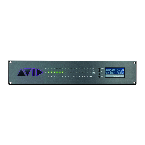
Chapter 5: Pro Tools | MTRX Front and Back Panels Pro Tools | MTRX Front Panel Pro Tools | MTRX front panel 16 LED indicators indicating signal level of analog input. 16 LED indicators indicating signal level of analog output. 4 buttons for operating the status display. - Page 24 Signal of AD channels 1–16. Yellow indicates signal input above –42 dB FS, and red indi- AD OL/Signal cates signal level above –0.5 dB FS. Signal of DA channels 1–16. Yellow indicates signal input above –42 dB FS. Green in- DA Signal/Carrier dicates signal below –42 dB FS and a valid digital input source/carrier.
- Page 25 Shows which external digital audio interface controls the sample rate, or it shows SRate Adapt Intern internal sample rate control. Shows the external synchronization clock source, or shows when the MTRX is using Sync Source Intern the internal clock. Shows the unit ID number and unit name. This is configured using DADman software. Unit ID /Name Shows the alarm status: Alarm/status...
- Page 26 Recovery Mode In Recovery mode only a basic boot software is operative in the unit, and new software can be downloaded using DADman software. This mode is used if the software in the MTRX is not operational or is otherwise malfunctioning.
-
Page 27: Pro Tools | Mtrx Back Panel
Pro Tools | MTRX Back Panel 100-240VAC, 50/60 Hz Max 90 VA Fuse T1AH/250VAC Slot Slot Slot Slot Slot Slot Slot Slot AES/EBU I/O 1-4 MADI Optical I/O WC/VBB AES11 in Net 1 Net 2 AES/EBU I/O 5-8 PHD I/O Primary 1 Pr 2/Exp 9 10... - Page 28 Digital I/O Connections MTRX Dual MADI I/O Expansion Card Optical I/O The MTRX Dual MADI I/O expansion card can be installed with one or two “Small form-factor plugga- ble” (SFP) transceiver modules. The SFP modules are standard types which support various types of opti- cal interfaces with LED or Laser diodes, various wavelengths and fiber types.
- Page 29 Ethernet, RJ45 Connector, Gigabit BI_DA+ Pin 1 BI_DA– Pin 2 BI_DB+ Pin 3 BI_DC+ Pin 4 BI_DC– Pin 5 BI_DB– Pin 6 BI_DD+ Pin 7 BI_DD– Pin 8 AES/EBU I/O 25-pin Female D-sub Connectors The top connector provides the connection for AES/EBU I/O 1–4 (stereo pairs 1–4 or mono channels 1–8).
- Page 30 Connections 1–4 / 5–8 Connections for the combined input and output 25-pin D-sub connector are listed in the table below. The pinning is according to the proprietary standard by Tascam. Pin number Function Pin number Function DOUT 4/8 + DOUT 4/8 – DOUT 3/7 + DOUT 3/7 –...
- Page 31 Analog I/O Connections Analog I/O 25-pin Female D-sub Connectors There are four types of optional analog cards for MTRX: 8-channel Line AD Card. Pro Tools | MTRX 8 Line Pristine AD card 2-channel Mic/Line AD Card. Pro Tools | MTRX 2 Mic/Line Pristine AD card 8-channel Mic/Line AD Card.
- Page 32 Connections for the 25-pin D-sub connector are listed in the table below. The pinning is according to the proprietary standard by Tascam. Pin number Function Pin number Function AIN/OUT 8 + AIN/OUT 8 – AIN/OUT 7 + AIN/OUT 7 – AIN/OUT 6 + AIN/OUT 6 –...
-
Page 33: Example System Configurations
Example System Configurations Chapter 5: Pro Tools | MTRX Front and Back Panels... - Page 34 Pro Tools | MTRX Installation Guide...
-
Page 35: Appendix A. Specifications
Appendix A: Specifications Audio Specifications Analog Input Sampling, resolution 5-bit sigma/delta @ 5.645 or 6.144 MHz, 24-bit PCM PCM (DXD) sample rates 44.1, 48, 88.2, 96, 174.4, 192, 352.8, 384 kHz DSD sample rates 8224 & 5.6448 Mhz (64 & 128 fs) Dynamic range (A) >... - Page 36 Analog Output Modulator resolution, format 32 x oversampling, 1 bit DSD, 24 bit PCM PCM (DXD) sample rates 44.1, 48, 88.2, 96, 174.4, 192, 352.8, 384 kHz DSD sample rates 8224 & 5.6448 Mhz (64 & 128 fs) Dynamic range (A) >...
-
Page 37: Electrical Specifications
DSD sample rates 8224 & 5.6448 Mhz (64 & 128 fs) Dynamic range (A) > 128 dB THD+N(A) < –110 dB @ –3 dB FS / 0.00031% Cross talk < 120 dB Max output level Adjustable from –60 dBu to 24 dBu in steps of 0.1 dB Network Interface Interface 1000BASE-T, RJ45 connector, 4-pair connection... -
Page 38: Mechanical Specifications
Mechanical Specifications Chassis standard 19”, 2 RU Chassis depth, without connectors mounted 35.0 cm / 13.8” Chassis body width 43.5 cm / 17.2” Weight, not including I/O cards 5 kg / 11 lbs. Chassis air flow from front to rear: Environmental Specifications Operating Temperature 0–45º... -
Page 39: Appendix B. Installing Mtrx Expansion Cards
Appendix B: Installing MTRX Expansion Cards The analog and digital I/O capacity, and processing of Pro Tools | MTRX can be expanded in the following ways: You can install up to six A/D or D/A cards in any combination, for up to 48 analog audio Analog I/O channels. -
Page 40: Preparing For The Installation
Preparing for the Installation Before installing expansion cards, collect the required materials and prepare your work area. To prepare for the installation: Make sure you have collected the required materials: • One or more MTRX Expansion Card packages. • Anti-Static wrist strap (not included). •... -
Page 41: Installing An Expansion Card
Installing an Expansion Card Installation steps differ slightly depending on the type of expansion card you are installing. If you are installing any of the following analog or digital I/O cards, or a processor card, see “Installing Expansion Cards” on page 31: •... - Page 42 To install an expansion card: Standing at the back of the unit, use a #1 Phillips screwdriver to remove the faceplate covering the slot where you want to install the card. For example, to install a card into slot 1 remove the two fasteners se- curing the faceplate on slot 1 shown below.
- Page 43 Align the PCIe connector on the card with the PCIe port mounted in the unit. Side view showing card PCIe connector aligned with unit PCIe port Making sure to guide the audio connectors through the open slot on the back of the unit, carefully push the card towards the back of the unit until it seats fully into its PCIe connector.
-
Page 44: Installing A Mtrx 64 Channel Ip Audio Dante Module
Installing a MTRX 64 Channel IP Audio Dante Module The MTRX 64-Channel IP Audio Dante Module is a small card that snaps into a slot on the motherboard. MTRX 64-Channel IP Audio Dante Module (top view) To install a MTRX 64-Channel IP Audio Dante Module: Locate the Dante card slot on the motherboard shown below. -
Page 45: Installing A Mtrx Madi Module
If necessary, gently push down on the card until it clicks into its two retaining clips. Pushing the Dante card down into its retaining clips Proceed to “Completing the Installation” on page 40. Installing a MTRX MADI Module The MTRX MADI module is a daughter card that is mounted to the motherboard. Installing a MADI mod- ule involves freeing the motherboard from the chassis, installing the MADI module onto its connector pins, then reattaching the motherboard assembly to the chassis. - Page 46 To install a MTRX MADI module: Remove the two fasteners that secure the faceplate over the Optical I/O slot and remove the faceplate. Set the screws aside (you will use them later to secure the card to the unit). Fasteners securing the Optical I/O faceplate The MTRX MADI module has been modified since its original production to make it easier to install.
- Page 47 Inside the unit, remove the five screws that secure the motherboard to the chassis. Fasteners to remove from the motherboard From the back of the unit, gently push the AES/EBU 5–8 and AES11 connectors towards the front of the unit, until the motherboard is no longer attached to the chassis. You should see and hear the Main Board multi-pin connector fully disengage.
- Page 48 Carefully position the MADI module in the unit so that the receiving holes on the underside of the MADI module align with the MADI connector pins on the motherboard. Side view of MADI module aligned with the connector on the motherboard With the card aligned, gently push the MADI module down so that it is fully seated on its connector.
- Page 49 Carefully move the motherboard back into its original position by doing the following: • Make sure the ports on the MADI module are aligned with the open Optical I/O slot of the back panel. Guide the ports through the slot while moving the motherboard back into position, if necessary. •...
-
Page 50: Completing The Installation
Completing the Installation After installing cards, reassemble the unit by replacing its top panel and then power on your system to con- firm the installation. To replace the top panel: Replace the top panel, making sure to orient it correctly so that the tabs on its front edge fit under the unit faceplate. -
Page 51: Appendix C. Warranty Claims Information
Appendix C: Warranty Claims Information If you experience a hardware failure within 30 days of purchase, you can return your product to your reseller for an exchange. For warranty claims, contact Avid directly: https://www.avid.com/learn-and-support/contact-audio-and-music-support For non-warranty claims, visit: http://avid.force.com/pkb/articles/faq/Avid-Audio-Product-Repairs Appendix C: Warranty Claims Information... - Page 52 Pro Tools | MTRX Installation Guide...
- Page 54 Technical Support (USA) Product Information Visit the Online Support Center Visit us on the web at www.avid.com/support www.avid.com...
Need help?
Do you have a question about the PRO TOOLS MTRX and is the answer not in the manual?
Questions and answers