Table of Contents
Advertisement
Quick Links
Advertisement
Table of Contents

Related Manuals for Eastwood 20521


Summary of Contents for Eastwood 20521
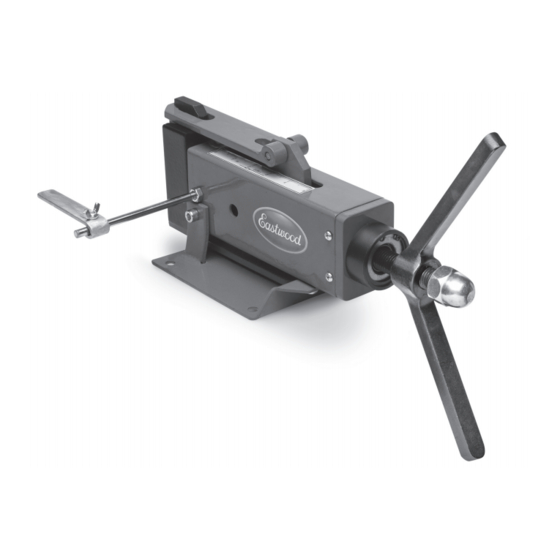
- Page 1 Part #20521 4" METAL BENDER INSTRUCTIONS...
-
Page 2: Specifications
The EASTWOOD 4” METAL BENDER is a high quality, industrial style tool capable of generating a powerful 2-1/2 tons of pressing force to create 90° or lesser repeatable bends in mild steel and aluminum up to 4” wide. INCLUDES (1) Metal Bending Brake Unit - [A] (1) Male Die –... -
Page 3: Safety Information
Before beginning ANY work with this tool, it is absolutely necessary that it be securely bolted to a heavy, sturdy, anchored workbench. To order parts and supplies: 800.345.1178 >> eastwood.com... - Page 4 To avoid injury, stop work immediately and inspect workpiece material for nicks, dents, welds, excessive scale or remaining coatings. Clean or repair as necessary or discard and begin with a new piece. Also inspect Metal Bender components for looseness or damage. Eastwood Technical Assistance: 800.544.5118 >> techelp@eastwood.com...
- Page 5 ASSEMBLY PINCH HAZARD! The Eastwood Metal Bender consists of moderately heavy metal components which can present a hand/finger pinch hazard and cause potentially serious injuries if dropped on feet. Avoid pinching hands while handling parts during assembly and wear thick, well- fitting work gloves to prevent cuts from handling sharp metal.
- Page 6 4. Slip Workpiece Stop [G] over Stop Rod [E], place Stop Clamping Screw [H] through hole then thread on Stop Clamping Wingnut [ I ]. The Eastwood Metal Bender is now ready to use. Eastwood Technical Assistance: 800.544.5118 >> techelp@eastwood.com...
-
Page 7: Operation
Avoid moving parts while operating and wear thick, well-fitting work gloves to prevent cuts from handling sharp metal. The use of safety shoes is strongly recommended. The Eastwood Metal Bender was specifically designed to be operated by one person only. Never have one person operate the Handle while one handles the material workpiece or serious injury could occur. - Page 8 If replacing, use a softer material 8mm pin or mild steel bolt (FIG 3). 2. As the desired bend is achieved, stop Clockwise rotation and reverse rotational direction of the Handle to release the completed workpiece. Eastwood Technical Assistance: 800.544.5118 >> techelp@eastwood.com...
- Page 9 2. To record the location of bend: Set the position of the Workpiece Stop Gauge [G] so that the point where the bend is to occur on the workpiece is determined by where the edge of the workpiece contacts the Stop Gauge (FIG 4). To order parts and supplies: 800.345.1178 >> eastwood.com...
-
Page 10: Maintenance
NOTE: The 8mm Shear Pin in the joint of the Drive Bar and Upper link is designed to fail under excess pressure. If replacing, use a softer material 8mm pin or mild steel bolt (FIG 4). Eastwood Technical Assistance: 800.544.5118 >> techelp@eastwood.com... - Page 11 To order parts and supplies: 800.345.1178 >> eastwood.com...
-
Page 12: Additional Items
Eastwood 24” Slip Roll If you have any questions about the use of this product, please contact The Eastwood Technical Assistance Service Department: 800.544.5118 >> email: techelp@eastwood.com PDF version of this manual is available online >> eastwood.com/20521manual The Eastwood Company 263 Shoemaker Road, Pottstown, PA 19464, USA US and Canada: 800.345.1178 Outside US: 610.718.8335...
Need help?
Do you have a question about the 20521 and is the answer not in the manual?
Questions and answers