Table of Contents
Advertisement
Quick Links
Advertisement
Table of Contents

Related Manuals for Eastwood 28135


Summary of Contents for Eastwood 28135
- Page 1 Item #28135 HEAVY DUTY METAL BENDER INSTRUCTIONS...
-
Page 2: Specifications
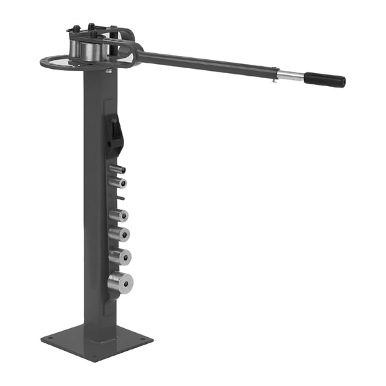
The Eastwood Heavy Duty Metal Bender is a high quality, industrial style tool capable of generating a powerful leveraged force to create 180° or greater repeatable bends in mild steel and aluminum up to 2" wide. CONTENTS COMPONENTS • (1) Base/Stand [A] (1) Ring Assembly/Die Receiver [B] •... -
Page 3: Safety Information
INJURY HAZARD! • The Eastwood Metal Bender is equipped with an Extension Handle for added bending force. DO NOT add pipe, bars or any other de- vices which would add additional length to the Handle to increase bending force. This will exceed the design limits of the tool and can result in serious injury and/or component failure. - Page 4 A minimum thickness of 2” concrete or 1” of a wood-based surface is strongly recommended. • Select an area for permanent location of the Eastwood Metal Bender. Allow a minimum of 4' of working area around the tool to allow for proper handle swing and operator space.
- Page 5 40mm Hitch Pin [J] through the holes and secure with the Pin Clip [K]. For projects requiring more leverage, remove the Pin Clip and Hitch Pin, extend the Handle, re-align the holes and reinstall the Pin Clip and Hitch Pin. • The Eastwood Metal Bender is now ready for use. FIG. 2...
-
Page 6: Operation
OPERATION The Eastwood Metal Bender is capable of producing a virtually endless configuration of bends and shapes. The purpose of this Instruction Booklet is intended to provide a full understanding of the functions of this tool and to assist the user in creating basic bends and shapes. More complex projects will require planning and some degree of “trial and error”. - Page 7 Assembly/Die Receiver [B] intersect (Fig 5). Die Location ORIENTATION OF HANDLE The Handle is always oriented Up and on the Right side. The Handle is always moved clockwise when a bend is being made. To order parts and supplies: 800.343.9353 >> eastwood.com...
- Page 8 NOTE: The workpiece will not need to be clamped when using the Right Angle Bending Attachment. Right-Angle-Bend • Mark the workpiece at the desired points to make a bend. Align the workpiece so that the Right Attachment Angle Bending Attachment [N] hits directly at the midpoint of your mark. Eastwood Technical Assistance: 800.343.9353 >> techelp@eastwood.com...
-
Page 9: Sample Projects
After becoming familiar with the Eastwood Metal Bender, a number of sample projects are presented on the following pages to increase proficiency and provide project ideas. - Page 10 Right Angle Bend Attachment (Fig 17). 7. With the workpiece tight against the Long Hitch Pin as close to center a s possible, make a right angle bend (Fig 17). FIG. 16 FIG. 17 Orientation Eastwood Technical Assistance: 800.343.9353 >> techelp@eastwood.com...
-
Page 11: Maintenance
NOTE: Maintenance should be performed before each use • Clean dirt and debris from all pivot points. • Check tightness of all hardware. • Check operation for binding. Lubricate moving parts periodically with medium bodied chassis grease. To order parts and supplies: 800.343.9353 >> eastwood.com... - Page 12 20254 – Eastwood 24" Slip Roll If you have any questions about the use of this product, please contact The Eastwood Technical Assistance Service Department: 800.343.9353 >> email: techelp@eastwood.com PDF version of this manual is available online >> eastwood.com/28135manual The Eastwood Company 263 Shoemaker Road, Pottstown, PA 19464, USA US and Canada: 800.343.9353...
Need help?
Do you have a question about the 28135 and is the answer not in the manual?
Questions and answers