Advertisement
Quick Links
Advertisement

Related Manuals for Gold Note Bellagio Reference


Summary of Contents for Gold Note Bellagio Reference
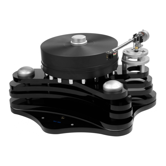
- Page 1 USER MANUAL BELLAGIO REFERENCE...
- Page 5 Thank you for purchasing one of our units and welcome into the Gold Note world, where we turn High-End audio and music into a new experience. Maurizio Aterini, founder of Gold Note...
-
Page 6: Important Safety | Informations
When a cart is used, use caution when moving the cart/apparatus combination to Gold Note does not have responsibility avoid injury from tip-over. for any improper use of this unit. Unplug this apparatus during lightning... - Page 7 Refer only to qualified Gold Note service personnel for service. GOLD NOTE - Information on the correct management of waste from household Equipment pursuant to the European Directive 2012/19/EU The crossed-out wheelie bin symbol shown on the equipment or its packaging indicates that the product, at the end of its useful life, must be collected separately from other waste to allow its proper treatment and recycling.
- Page 9 | INDEX INTRODUCTION AND FEATURES TECHNICAL SPECIFICATIONS UNBOXING ASSEMBLING THE TURNTABLE POWER SUPPLY SPEED CONTROL & FUNCTIONS VTA AND AZIMUTH SETUP CARTRIDGE AND TONEARM CALIBRATION PRODUCT REGISTRATION TROUBLESHOOTING RELATED PRODUCTS...
-
Page 10: Introduction And Features
The new hourglass-shaped motor pulley stops the transmission of any vibration thanks to its dampening qualities. It’s The power supply of the Bellagio Reference precisely machined and then polished to electronically controls the 33 rpm and... -
Page 11: Technical Specifications
| TECHNICAL SPECIFICATIONS MAIN FEATURES DIMENSIONS AND WEIGHT Wow & flutter: Dimensions: 0,05% 530mm W 350mm H 500mm D Rumble: Weight: -83db 32Kg Speed: FINISHES rpm and 45 rpm ±0,1% UPPER PLINTH: Speed changing: Black polished acrylic Electronic with fine pitch control MAIN PLINTH: Transmission: Black polished acrylic and titanium... - Page 12 | UNBOXING LAYER A Platter with 18 counterweights (already Tonearm flange assembled) Platter clamp Conical spacer for tonearm flange (3x) Turntable foot (3x) Tonearm board with adapter (already assembled) Platter spindle clamp Threaded bar sleeve (3x) Motor...
- Page 13 LAYER B Upper plinth Tonearm flange bottom support (3x) Titanium threaded bar with nut (3x) Dome cover (2x) (already assembled) Titanium support for the upper plinth Conical cover (3x)
- Page 14 LAYER C Main plinth...
- Page 15 LAYER D BOX 1 BOX 2 Transmission belt (2x) PST-10 power supply Oil for the spindle/bearing Felt mat 13mm titanium wrench Stroboscope 10mm titanium L wrench BOX 3 5mm Allen wrench Power cord 3mm Allen wrench 2mm Allen wrench 6x60mm Allen screws (for the motor) (2x) 4x40mm Allen screws (for the arm board) (3x)
-
Page 16: Assembling The Turntable
| ASSEMBLING THE TURNTABLE STEP 1 Take the titanium threaded bars located in B2 (layer B, number 2), these have already been assembled as shown in the image and are ready to be used. PLEASE NOTE: Each bar has two O-rings already installed and the nut, these should be spaced as shown in the image below. - Page 17 STEP 2 STEP 2.1 Screw the bars into the main plinth with the side B facing downwards and going into the plinth. Side A, where the O-rings are located, faces upwards. STEP 2.2 On the bottom side of the main plinth, the bars should protrude for 15mm.
- Page 18 STEP 3 Take the 3 feet located in A3 (layer A, number 3) and install them screwing them on the threaded bars as shown in the pictures below.
- Page 19 STEP 4 Top side Take the 3 threaded bar sleeve located in A9. Install them ensuring the open side faces down and slide them onto the threaded bars as shown in the pictures below. Bottom side...
- Page 20 STEP 5 Take the titanium supports for the upper plinth located in B3. Install the supports on the bars by screwing them until they touch the sleeves.
- Page 21 STEP 6 Take the motor located in A5 and the 6x60 Allen screws (2x) located in the BOX 1 of the layer D. STEP 6.1 Connect the power cable installed on the main plinth to the motor, the connector is located on the bottom side of the motor.
- Page 22 STEP 6.2 STEP 6.3 Insert the Allen screws into the slots located Ensure that the screws are centred and use on each side of the cable on the main plinth the 5mm Allen wrench to lock the motor in ensuring that the head is on the bottom of place.
- Page 23 STEP 7 Prepare the upper plinth, which is located in B1. Carefully lower the plinth onto the support bars ensuring that the areas for the pulley and the motor are cleared. Please take extra care as the plinth and motor can be accidentally damaged.
- Page 24 STEP 8 Take the platter located in A1 and the platter spindle clamp located in A4. Install the platter on the upper plinth, pay attention to center it on the spindle - it should fit perfectly.
- Page 25 STEP 8.1 Insert the platter spindle clamp into the platter center and screw it into the spindle until locked.
- Page 26 STEP 9 Prepare the following parts to assemble the tone arm support: Tonearm flange, located in A6 3 conical spacers for tonearm flange, located in A7 Tonearm board with adapter, located in A8 3 supports for the tonearm flange, located in B4 3 4x40mm Allen screws (for the arm board), located in D1...
- Page 27 STEP 9.4 STEP 9.1 Install the supports for the tonearm flange screwing them into the upper plinth as shown in the picture. STEP 9.2 Lay the tonearm flange on top of the supports paying attention that the holes STEP 9.3 of the flange are aligned with those of the supports.
- Page 28 STEP 10 Take the transmission belt located in the BOX 1 of the Layer D. Wrap the belt around the pulley first and then around the platter as shown in the picture. The belt must be positioned on the lower platter, close to the counterweights and horizontally aligned with the pulley.
- Page 29 STEP 11 Check if the turntable is horizontally levelled Rotate clockwise to lower the plinth on the with the help of a spirit level. axis, and counterclockwise to raise it. To adjust the levelling, use the 10mm L wrench and rotate clockwise or counterclockwise the titanium supports installed at STEP 5.
- Page 30 STEP 12 Take the 2 dome covers located in B5 and the conical cover located in B6. Insert the dome covers onto the titanium supports located in front of the platter and the conical cover on the support located at the back.
- Page 31 Connect the mini-XLR cable to the dedicated specifically designed for our turntables, a port highlighted in the picture. Remember to perfect match for the Bellagio Reference. switch on the PST-10 using the master switch The power supply is already set for the located on the rear of the unit.
- Page 32 FUNCTIONS SPEED CONTROL STANDBY The Bellagio Reference features an electronic To put the Bellagio Reference on standby speed control with dedicated buttons for the mode, press and keep pressed both buttons rpm and 45rpm modes. for 3” while the turntable is not playing.
- Page 33 VTA SETUP To up or down the arm by correctly adjusting the VTA, use the 1.5 mm Allen key supplied by Gold Note and insert it in the three holes on the arm board indicated by the arrows. AZIMUTH After the cartridge has been properly...
- Page 34 CARTRIDGE AND TONEARM | CALIBRATION Our turntables and tone arms are always supplied with the Gold Note Calibration Tool to calibrate correctly the setup. With this tool you will be able to adjust: Phono Cartridge alignment. Overhang. 45rpm and 33 rpm speed (requires a strobe light).
- Page 35 ALIGNMENT To correctly align the phono cartridge and achieve the best tracking position, point the tip of the phono cartridge into the circles as in the picture below. The body of the phono cartridge must be aligned to the vertical stripes in order to achieve the best position for musical reproduction.
-
Page 36: Product Registration
Any service and inspection must be carried out by a Gold Note dealer or distributor so If the unit is not registered correctly or has in case you need any assistance with this been purchased from a different country of product, please contact the seller. -
Page 37: Troubleshooting
| TROUBLESHOOTING PROBLEM CAUSE SOLUTION Levelling the turntable. The turntable is not With a spirit level, only levelled. level the Turntable Platter through its shelf layer eventually screwing its feet just for very fine adjustment, take care of levelling the platter on its vertical and horizontal lines. -
Page 38: Related Products
| RELATED PRODUCTS CARTRIDGES LOUDSPEAKERS TUSCANY XS-85 Our top-of-the-line MC cartridge, the result Our flagship loudspeaker, a full-range of over 20 years of experience, boasts an 3-way design featuring a bass reflex port, extra-thin Micro Ridge diamond tip and top-quality crossover and the best materials precisely hand-wrapped coils. - Page 40 Designed and handmade in Firenze, Italy www.goldnote.it service@goldnote.it copyright ©2021 Akamai S.r.l. All rights reserved...
Need help?
Do you have a question about the Bellagio Reference and is the answer not in the manual?
Questions and answers