Advertisement
Quick Links
Advertisement

Related Manuals for Gold Note Bellagio Conquest


Summary of Contents for Gold Note Bellagio Conquest
- Page 1 Bellagio Conquest OWNER’S MANUAL...
-
Page 3: Important Safety Information
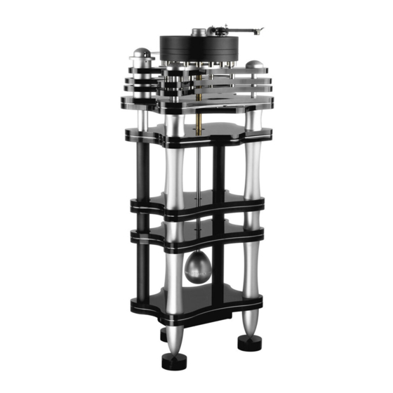
IMPORTANT SAFETY INFORMATION 1 Read these instructions. normally, or has been dropped. 2 Keep these instructions. • Do not expose this apparatus to drips or splashes. • Do not place any objects filled with liquids, such as vases, on 3 Heed all warnings. the apparatus. - Page 4 The amazing length of the turntable spindle guarantees the smoothest platter rotation available and force distribution control along the spindle axis to enhance unsurpassed audio performance. All Gold Note products are proudly designed, manufactured and assembled in Italy 100% OWNER’S MANUAL page 3...
- Page 5 CONTENT OF PACKAGING: Layer A1 1) 110mm thick Platter made of Sustarin Acetamide with counterweights (1x) 2) Platter Clamp (1x) 3) 270mm Bronze bearing and C40 rectified polished Spindle (1x) 4) Platter Spindle Tip (1x) 5) Motor Cylinder with motor Pulley (1x) 6) Tone Arm Bottom Flange (1x) 7) Tone Arm Flange Conical Spacers (3x) 8) Tone Arm Board with adapter...
- Page 6 CONTENT OF PACKAGING: Layer A2 1) Top three layer black acrylic plinth (1x) 2) Threaded Titanium bar (3x) 3) Top Plinth Conical Support (3x) 4) Tone Arm Flange Bottom Support (3x) 5) Front Aluminium Conical Support Cover (2x) 6) Rear Conical Support Cover (1x) OWNER’S MANUAL page 5...
- Page 7 CONTENT OF PACKAGING: Layer A3 1) CPU black acrylic double plinth with display and keyboard to control the turntable (1x) OWNER’S MANUAL page 6...
- Page 8 CONTENT OF PACKAGING: Layer A4 1) Lower CPU black acrylic double Plinth/Top plinth of the integrated turntable stand (1x) 2) Aluminium sleeve for power supply 3) Aluminium sleeve for tonearm cable OWNER’S MANUAL page 7...
- Page 9 CONTENT OF PACKAGING: Layer B1 1) 1° Black Acrylic Middle double plinth part of Integrated stand (1x) 2) Long aluminium threaded legs (6x) 3) Top aluminium threaded legs (3x) OWNER’S MANUAL page 8...
- Page 10 CONTENT OF PACKAGING: Layer B2 1) 2° Black Acrylic Middle double plinth part of Integrated stand (1x) OWNER’S MANUAL page 9...
- Page 11 CONTENT OF PACKAGING: Layer B3 1) Bottom black acrylic double plinth (1x) 2) Short Aluminium Threaded Legs (x3) OWNER’S MANUAL page 10...
- Page 12 CONTENT OF PACKAGING: Layer B4 1) Giant Aluminium stand feet (3x) 2) Rocker Arm Counterweight (1x) 3) Aluminium Platter Bearing blocking Nut (1x) 4) Bronze threaded junction (1x) OWNER’S MANUAL page 11...
- Page 13 CONTENT OF PACKAGING: Layer B5 At the top of the layer you found: - Felt Mat (1x) - Stroboscope (1x) 1) Cable Pipe (2x) - 5mm Allen wrench for Motor fixing screws (1x) 2) Rocker Arm Stainless Steel bar (1x) - 6x60mm Motor Allen Screws (2x) 3) 100x40mm adjustable foot washers (3x) - 4x40mm Arm Board Allen Screws (3x)
- Page 14 ASSEMBLING THE TURNTABLE STAND STEP 1 For the STEP 1 take the following parts: (3x) Giant Aluminium stand Foot located located in the layer B4 position 1x Bottom black acrylic double plinth located in the layer B3 position 1 STEP 1-1 Place the plinth on a soft flat surface on floor and carefully insert the first foot on the rear hole (at the center) of the plinth as shown in the picture.
- Page 15 ASSEMBLING THE TURNTABLE STAND STEP 2 For the STEP 2 you need these parts: (3x) Long Aluminium Threaded leg in the layer located in B1 position 2 STEP 2-1 Screw the threaded legs one at a time as show in the pictures. Use the grease supplied (B5 position 5) to install the legs more easily.
- Page 16 ASSEMBLING THE TURNTABLE STAND STEP 3 For the STEP 3 you need these parts: (3x) 100x40 Adjustable Foot Washer located in the layer B5 position 3 STEP 3-1 Install the foot washers underneath each foot. Once done, level horizontally the base of the stand by rotating clockwise or anti-clockwise the washers.
- Page 17 ASSEMBLING THE TURNTABLE STAND STEP 4 For the STEP 4 you need this part: 1° Black Acrylic Middle double plinth part of Integrated stand (1x) located in B1 position 1 Simply lay down the Black Acrylic Middle double plinth being sure to face up the polished side without any blocking screws STEP 4 COMPLETED OWNER’S MANUAL...
- Page 18 ASSEMBLING THE TURNTABLE STAND STEP 5 For the STEP 5 you need these parts: (3x) Short Aluminium Threaded Leg located in B3 position 2 STEP 5-1 Screw the threaded legs one at a time as show in the pictures with the help of the grease supplied.
- Page 19 ASSEMBLING THE TURNTABLE STAND STEP 6 For the STEP 6 you need these parts: 2° Black Acrylic Middle double plinth part of Integrated stand (1x) located in B2 position 1 STEP 6 COMPLETED OWNER’S MANUAL page 18...
- Page 20 ASSEMBLING THE TURNTABLE STAND STEP 7 For the STEP 7 you need these parts: (3x) Long aluminium threaded leg in the layer located in B1 position 2 STEP 7-2 STEP 7-1 STEP 7-3 STEP 7 COMPLETED OWNER’S MANUAL page 19...
- Page 21 ASSEMBLING TURNTABLE STAND [Cable Pipes] STEP 8 For the STEP 8 you need these parts: Cable Pipe (2x) located in B5 position 1 STEP 8 Feed the cable pipes into the rear holes of the stand. They will be used to cover the cables of the power supply, the motor and eventually the main tonearm cable.
- Page 22 ASSEMBLING THE TURNTABLE STAND STEP 9 For the STEP 9 you need this part: Lower CPU black acrylic double Plinth/Top plinth of the integrated turntable stand (1x) located in A4 position 1 STEP 9 COMPLETED OWNER’S MANUAL page 21...
- Page 23 ASSEMBLING TURNTABLE STAND [CPU supports] STEP 10 For the STEP 10 you need these parts: (3x) Top Aluminium Threaded leg located in B1 position 3 STEP 10-2 STEP 10-1 STEP 10 COMPLETED STEP 10-3 OWNER’S MANUAL page 22...
- Page 24 ASSEMBLING TURNTABLE STAND [Cable Covers & Rocker Weight Bar] STEP 11 For the STEP 11 you need these parts: Rocker Arm Stainless Steel bar (1x) located in B5 position 2 Aluminium sleeve for power supply and sleeve for tonearm cable located in A4 position 2 and 3 Bronze threaded junction located in B4 position 4 STEP 11-1...
- Page 25 ASSEMBLING TURNTABLE [CPU Plinth] STEP 12 For the STEP 12 you need these parts: CPU black acrylic double plinth with display and keyboard to control the turntable (1x) located in A3 position 1 STEP 12-1 Insert the cable of the CPU plinth into the Cable Pipe as shown in the picture aside.
- Page 26 ASSEMBLING TURNTABLE [CPU Plinths] STEP 12 STEP 12-3 Ensure to center the black acrylic double plinth on the threaded legs. PLEASE NOTE: The cable must be fed into the pipe as shown in the detailed picture. STEP 12 COMPLETED OWNER’S MANUAL page 25...
- Page 27 ASSEMBLING TURNTABLE TOP PLINTH [Threaded Bars] STEP 13 For the STEP 13 you need these parts: Threaded Titanium bar (3x) located in layer A2 position 2 STEP 13-2 Screw the titanium threaded bars with the Nuts/ Washers facing down into the plinth. STEP 13-3 Tighten the nuts with the 13mm Wrench supplied (B5 position 5).
- Page 28 ASSEMBLING TURNTABLE TOP PLINTH [Sleeves] STEP 14 For the STEP 14 you need these parts: Sleeves (3x) located in A1 position 9 STEP 14 Insert the sleeves on the titanium threaded bar. (this side UP) Bottom STEP 14 COMPLETED OWNER’S MANUAL page 27...
- Page 29 ASSEMBLING TURNTABLE TOP PLINTH [Top Plinth Conical Supports] STEP 15 For the STEP 15 you need these parts: Top Plinth Conical Supports (3x) located in A2 position 3 STEP 15 Install and tighten the conical supports on the titanium threaded bars. Leave around 5mm between the bottom of the supports and the top of the sleeves.
- Page 30 ASSEMBLING TURNTABLE TOP PLINTH [Motor] STEP 16 For the STEP 16 you need these parts: Motor Cylinder completed with motor Pulley (1x) located in A1 position 5 Motor Allen Screws with Nylon Washers (2x) located in B5 position 5 STEP 16-1 Plug the other side of the Motor cable Mini XLR connector into the bottom of Motor as shown in the picture aside.
- Page 31 ASSEMBLING TURNTABLE TOP PLINTH [Triple Plinth] STEP 17 For the STEP 17 you need these parts: Triple Plinth located in A2 position 1 STEP 17-1 Carefully lower the plinth onto the support bars ensuring that the areas for the pulley and the motor are cleared.
- Page 32 ASSEMBLING TURNTABLE TOP PLINTH [Triple Plinth] STEP 17 STEP 17-2 With the 3mm Allen wrench located in B5 position 5 remove the three screws as shown in the picture aside STEP 17-3 Remove the Platter Flange as indicated in the picture aside OWNER’S MANUAL page 31...
- Page 33 ASSEMBLING TURNTABLE TOP PLINTH [Platter Flange] STEP 18 For the STEP 18 you need these parts: 270mm Bronze bearing and C40 rectified polished Spindle (1x) located in A1 position 3 Aluminium Platter Bearing blocking Nut (1x) located in B4 position 3 STEP 18-1 Insert the 270mm bearing/spindle into the platter flange.
- Page 34 ASSEMBLING TURNTABLE TOP PLINTH [Platter Flange] STEP 19 STEP 19-1 Insert the Platter Flange back in its original position as shown in the picture aside STEP 19-2 Thighten the three platter Flange screws previously removed with the 3mm Allen wrench located as shown in the picture aside OWNER’S MANUAL...
- Page 35 ASSEMBLING TURNTABLE TOP PLINTH [Platter/Spindle] STEP 20 For the STEP 20 you need these parts: 110mm thick Platter made of Sustarin Acetamide and 16 peripheral counterweights (1x) located in A1 position 1 Platter Spindle Tip that clamps the platter (1x) located in A1 position 4 STEP 20-1 Install the platter on the upper plinth, pay...
- Page 36 ASSEMBLING TURNTABLE TOP PLINTH [Tonearm Flange/Board] STEP 21 For the STEP 21 you need these parts: Tonearm flange located in A1 position 6 3 conical spacers for tonearm flange located in A1 position 7 Tonearm board with adapter located in A1 position 8 3 supports for the tonearm flange located in A2 position 4 3 Allen screws 4x40mm(for the arm board) located in B5 position 5 STEP 21-1...
- Page 37 ASSEMBLING TURNTABLE TOP PLINTH [Tonearm Flange/Board] STEP 21 PLEASE NOTE The flange adapter is designed out of axis to guarantee the compatibility with 9” tonearms. To change the position of the adapter, you can rotate it in order to fit your tonearm. Use the 2mm Allen wrench to lock and unlock the adapter.
- Page 38 ASSEMBLING TURNTABLE TOP PLINTH [Transmission Belt] STEP 22 STEP 22-1 Wrap the belt around the pulley first and then around the platter as shown in the picture. The belt must be positioned on the lower platter, close to the counterweights and horizontally aligned with the pulley.
- Page 39 ASSEMBLING TURNTABLE TOP PLINTH [Levelling] STEP 23 STEP 23-1 Check if the turntable is horizontally levelled with the help of a spirit level. To adjust the levelling, use the 10mm L wrench and rotate clockwise or counterclockwise the titanium supports installed at STEP 5.
- Page 40 ASSEMBLING TURNTABLE TOP PLINTH [Dome Covers] STEP 24 STEP 24-1 Take the 2 dome covers located in A2 position 5 and the conical cover located in A2 position 6 Insert the dome covers onto the titanium supports located in front of the platter and the conical cover on the support located at the back.
- Page 41 ASSEMBLING TURNTABLE [Rocker Arm Counterweight] STEP 25 For the STEP 25 you need these parts: Rocker Arm Counterweight (1x) located in B4 position 2 STEP 25-1 STEP 25-2 Connect the rocker arm to the platter bearing/spindle Once the rocker arm has been secured to the using the bronze threaded junction.
-
Page 42: Power Supply
POWER SUPPLY STEP 24-1 The PST-10 is our best power supply specifically designed for our turntables, a perfect match for the Bellagio Reference. The power supply is already set for the Bellagio so you simply need to connect it to the power outlet and the motor. Connect the mini-XLR cable to the dedicated port highlighted in the picture. - Page 43 SPEED CONTROL AND FUNCTIONS SPEED CONTROL STANDBY The Bellagio Reference features an To put the Bellagio Reference on standby electronic speed control with dedicated mode, press and keep pressed both buttons buttons for the 331/3rpm and 45rpm for 3” while the turntable is not playing. modes.
- Page 44 VTA, use the 1.5 mm Allen installed on the tone arm, you can adjust key supplied by Gold Note and insert it in the angle of the headshell with the the three holes on the arm board indicated supplied 0,9 mm Allen Wrench.
- Page 45 CARTRIDGE AND TONEARM CALIBRATION VTA SETUP Our turntables and tone arms are always supplied with the Gold Note Calibration Tool to calibrate correctly the setup. With this tool you will be able to adjust: A Phono Cartridge alignment. B Overhang.
- Page 46 CARTRIDGE AND TONEARM CALIBRATION ALIGNMENT To correctly align the phono cartridge and achieve the best tracking position, point the tip of the phono cartridge into the circles as in the picture below. The body of the phono cartridge must be aligned to the vertical stripes in order to achieve the best position for musical reproduction.
-
Page 47: Product Registration
Any service and inspection must be carried out by a Gold Note dealer or distributor so If the unit is not registered correctly or has been in case you need any assistance with this purchased from a different country of the product, please contact the seller. - Page 48 MOTOR HEATING The Motor warms up • AC synchronous motors as the too much ones used by Gold Note may warm up to 50° Celsius without creating any problem •Gently lift the pulley up a bit •The pulley’s shaft slightly touches...
- Page 49 FAQ AND TROBLESHOTING SYMPTOM DESCRIPTION CAUSE REMEDY OIL POORED FROM Oil drops come out • The pressure created by the • Clean it up, the oil will never comes BRONZE BEARING the bottom Platter strict tolerance of the out again once the Platter spindle is Bearing when the Bearing/Spindle system can let perfectly positioned into the Platter...
- Page 50 USER NOTE OWNER’S MANUAL page 49...
- Page 51 USER NOTE OWNER’S MANUAL page 50...
Need help?
Do you have a question about the Bellagio Conquest and is the answer not in the manual?
Questions and answers