
Related Manuals for Ludlum Measurements 3277


Summary of Contents for Ludlum Measurements 3277
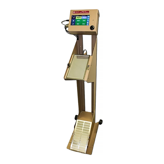
- Page 1 Model 3277 Hand and Foot Monitor Ludlum Measurements October 2020 Firmware: 1.10.2 and Higher...
- Page 3 Model 3277 Hand and Foot Monitor Ludlum Measurements October 2020 Firmware: 1.10.2 and Higher...
- Page 5 STATEMENT OF WARRANTY Ludlum Measurements, Inc. warrants the products covered in this manual to be free of defects due to workmanship, material, and design for a period of twelve months from the date of delivery. The calibration of a product is warranted to be within its specified accuracy limits at the time of shipment.
-
Page 7: Table Of Contents
ONTENTS Contents List of Figures List of Tables 1 Introduction 2 Getting Started Unpacking and Repacking ....... 11 2.1.1 Powering the Unit . - Page 8 Model 3277HFM System ....... . 47 10 Recycling Ludlum Measurements, Inc.
-
Page 9: List Of Figures
IST OF IGURES Splash-screen/Wallpaper ........12 System Idle ......... . 13 Readings . -
Page 11: List Of Tables
IST OF ABLES Power Status ......... 14 Run Mode Buttons . -
Page 13: Introduction
Two large scintillating detectors are mounted to allow detection on the hand and foot. Since the detectors in the Model 3277 are scintillators, there is no gas to maintain. An optional third detector is also available for frisking. The detection circuitry of the Model 3277 is powered by Model 3002 main boards. -
Page 15: Getting Started
Check individual item serial numbers and ensure calibration certificates match between instruments and de- tectors (if applicable). The Model 3277 serial number is located on the bottom left corner of the front face of the unit. -
Page 16: Instrument Operational Test
7. Plug transformer into wall. 8. Set the power switch to the ON position. Some versions of the Model 3277 do not have a power switch. These units should boot up as soon as power is connected. 2.2 Instrument Operational Test After powering on the instrument, it should start booting. -
Page 17: Instrument Use And Controls
Once this procedure has been completed, the instrument is ready for use. 2.3 Instrument Use and Controls With the color touch-screen display, the Ludlum Model 3277 is simple and easy to use with minimal training required. While in normal running mode, the unit will look similar to Fig- ure 2.2. -
Page 18: Status Bar
Running on battery power and battery is low Crit. Bat: Running on battery and battery is very low, will shutdown very soon Supply: Supply voltage, battery telemetry is not available <No Status> Battery and supply voltages not available Ludlum Measurements, Inc. -
Page 19: Button Bar
2.3. INSTRUMENT USE AND CONTROLS 2.3.3 Button Bar The button bar (Figure 2.5) shows the main controls/indicators for the current state of oper- ation. Table 2.2 describes the general function of the buttons that can be seen during normal operation. Figure 2.5: Button Bar Table 2.2: Run Mode Buttons Settings Menu... -
Page 20: Run Mode Icons And Tap Controls
Current readings are count Return to rate readings Manual touch control can be disabled in settings Some buttons have extended features by pressing, holding for more than 1 second, and then releasing. Table 2.4 lists their functions. Ludlum Measurements, Inc. -
Page 21: Detector Sensors
Show current background values 2.4 Detector Sensors The Ludlum Model 3277 has sensors for the hand (Figure 2.6), foot (Figure 2.7), and optional cradle (Figure 2.8). When these sensors are activated, the hand/foot/frisker icons on the display will light up to indicate the sensor has been activated. -
Page 22: Detector Fail Diagnostics
CHAPTER 2. GETTING STARTED 2.5 Detector Fail Diagnostics Note that the Model 3277 has its own diagnostic tests to ensure that the detector is func- tioning correctly. The Model 3277 can detect when the radiation detector is malfunctioning and will display an error. If the detector stops detecting radiation for a settable number of seconds, the Model 3277 will display "LOC"... -
Page 23: Normal Operation
3.1 Idle State "Idle" for the Model 3277 is defined as the normal condition the unit is in when the frisker is in the cradle, the hand and foot sensors are not triggered, and the unit is not in a source check lockout. -
Page 24: Idle Rate
An automatic count is started when both hand and foot sensors are activated. When this state is triggered, the unit will automatically start a count who’s count time is calculated via the MCT function. See Chapter 5 for details. Ludlum Measurements, Inc. - Page 25 3.4. AUTO COUNT If the count mode alarm points are not set through Calibration Software, the Model 3277 is unable to calculate a time to count for and will therefore not au- tomatically start a count. October 2020...
-
Page 27: Backup Battery
If the unit is powered from batteries until shutdown and left disconnected from wall power, a new battery can become discharged below 7 volts within 4 days. Ludlum Measurements, Inc. recommends replacing the batteries every four years. The following sections describe various maintenance procedures that may need to be performed on the battery. -
Page 28: Connecting Battery
2. Locate the red and black terminal as well as the red and black battery wires. 3. Connect the red wire with the to the red (positive) terminal. 4. Connect the black wire to the black (negative) terminal. 5. Replace cover and screws. Ludlum Measurements, Inc. -
Page 29: Recovering Overly Discharged Battery
7. Reconnect instrument connections. 8. Replace cover and screws. 9. Immediately plug Model 3277 into wall power and allow unit to fully charge the battery. You can turn the instrument on to monitor the battery voltage and verify it is charging by monitoring the battery voltage displayed in the top right corner of the display. -
Page 30: Replacing Battery
5. Remove foam from old battery and reuse foam or replace foam on new battery. Ensure temperature probe is wrapped inside touching battery, near middle of battery. 6. Install new battery and battery strap. 7. Tighten nuts. 8. Reconnect instrument connections. 9. Replace cover and screws. Figure 4.3: Battery Mounting Screws Ludlum Measurements, Inc. -
Page 31: Minimum Count Time
INIMUM OUNT The Minimum Count Time (MCT) is intended to achieve maximum user throughput for a fixed Minimum Detectable Activity (MDA) requirement. MCT calculates the time required to count based on the background average, MDA (set via the Model 3002 alarm point), and detection probability. -
Page 32: Mct Count Starting
If the user removes their hand and/or foot from the detectors before a count is complete, the count will be aborted and a count incomplete message (Figure 5.5) will be displayed. Ludlum Measurements, Inc. -
Page 33: Mct Count Completed - Clean
5.1. OPERATION Figure 5.3: MCT Count Completed - Clean Figure 5.4: MCT Count Completed - Alarm Figure 5.5: MCT Count Incomplete October 2020... -
Page 34: Minimum Count Time (Mct) Algorithm
The minimum count time is calculated by iterating through the number of sample count seconds and using Equations 5.1, 5.2, 5.3, and 5.4 until the MDA is greater than or equal to the count alarm value set on the detector board. Ludlum Measurements, Inc. -
Page 35: Source Check
OURCE HECK A source check feature can be enabled on this instrument. See subsection 7.2.4 for settings to enable the source check. If the source check is enabled and expired, the instrument will be out of service until a source check is successfully passed. If the source check feature is disabled or the source check is current, the instrument will operate normally. -
Page 36: Start Source Check
final one to complete the source check, there will be a dialog (Figure 6.5) informing the user that all tests have been completed and detailing how long until the next source check is required. Ludlum Measurements, Inc. -
Page 37: Source Check - Source Selection
6.1. PERFORMING A SOURCE CHECK Figure 6.2: Source Check - Source Selection Figure 6.3: Source Check - Start Count Figure 6.4: Source Check - Results October 2020... -
Page 38: Source Check - Current
CHAPTER 6. SOURCE CHECK Figure 6.5: Source Check - Current Ludlum Measurements, Inc. -
Page 39: Settings
Calibration is not accessed through the settings menu. See Chapter 8 for details. The Model 3277 has two user levels. The top level has the options to configure how the instruments perform. The second user level is for performing a source check. -
Page 40: Settings - Login
The user login screen looks like Figure 7.1. Click in the box to the right of "User ID" to bring up the keypad. Figure 7.1: Settings - Login Tap in the desired user ID from Table 7.1 and press the enter button (">") on the bottom right of the keyboard. Ludlum Measurements, Inc. -
Page 41: Settings Menus
7.2. SETTINGS MENUS Figure 7.2: Settings - Keypad Figure 7.3: Settings - Enter User ID 7.2 Settings Menus The following subsections list each of the menu pages. These menus can be cycled through by clicking the up and down arrows after logging in. 7.2.1 General Settings The general settings page is for configuring the basic operation of the instrument. -
Page 42: Idle Settings
Alarm point for alpha and beta Alpha and Beta Integer alarms in each detector (Only Alarms applies when idle) The units for the alarm points are controlled by the detector board’s rate mode settings. Ludlum Measurements, Inc. -
Page 43: Mct Settings
7.2. SETTINGS MENUS 7.2.3 MCT Settings The minimum count time (MCT) function is controlled with the following settings. See Chapter 5 for more details on MCT functionality. Table 7.5: MCT Settings Setting Options Details Selects confidence required for Confidence <percentage> calculating minimum count... -
Page 44: Set Time
Current day of the month Year Integer Current year Pressing button sets the system Set Time Go Button time and time zone to the cur- rent settings 7.3 Info Menu This menu can be accessed by clicking on the info icon. Ludlum Measurements, Inc. -
Page 45: System Control Menu
7.4. SYSTEM CONTROL MENU Table 7.8: Info Setting Options Details The name used by this device Hostname <read only> when connected to the network IP address of this device when IPv4 <read only> connected to the network Pressing button will attempt to Upgrade Web Button download and install an update... -
Page 47: Detector Board Calibration/Configuration
8.1 Required for operation Table 8.1 describes the parameters every detector board (Model 3002 board) must be con- figured to for proper operation of the Model 3277. These should all be set correctly at the factory and are listed here for reference. -
Page 48: Calibration Parameters
Sets the discrimination voltages for the alpha and beta chan- & Windows nels Efficiency Defines the detection efficiency of the detector Defines the unit shown while the Model 3277 is idle in the Rate Units "Rate" mode Count Units Defines the unit shown while in all "Counting" modes Rate Alarm Alarm value while the Model 3277 is idle in the "Rate"... -
Page 49: Idle Alarm Values
MCT result. 8.2.4 Ignored Parameters Table 8.3 lists the parameters that are ignored and/or overridden by the Model 3277. Table 8.3: Ignored Parameters Parameter... -
Page 51: Specifications
PECIFICATIONS 9.1 Model 3277HFM System Part Number 48-4333-1 • DISPLAY: 17.8 cm (7 in.) diagonal, TFT LCD SVGA • COUNT TIME: automatic and manual count modes • CONTROLS: touch screen, IR hand/foot sensors • ALARMS: audible and visual alarms • CLICK AUDIO: greater than 75 dB at 0.6 m (2 ft.), approximately 4.5 kHz •... - Page 52 * EFFICIENCY (4 ): · Alpha - Pu - 12% · Beta - Tc - 10% * TYPICAL BACKGROUND: · Alpha - 7 cpm · Beta - 1000 cpm * CROSS-TALK: · Alpha to Beta · Beta to Alpha Ludlum Measurements, Inc.
- Page 53 9.1. MODEL 3277HFM SYSTEM • OPTIONS: – Model 43-93 Alpha-Beta Frisker: (PN: 4519-277) Includes Model 43-93 detector and cradle with switch – Model 43-147 Alpha-Beta Frisker: (PN: 4519-489) Includes Model 43-147 detec- tor and cradle with switch – Battery Backup: (PN: 4224-043) * Input: 12-15 Vdc, 24 W;...
-
Page 55: Recycling
To this end, Ludlum Measurements, Inc. strives to supply the consumer of its goods with information regarding reuse and recycling of the many different types of materials used in its products.
Need help?
Do you have a question about the 3277 and is the answer not in the manual?
Questions and answers