
Related Manuals for Ludlum Measurements 375


Summary of Contents for Ludlum Measurements 375
- Page 1 LUDLUM MODELS 375 (INCLUDING SERIES ONE), 375/1, 375/2 AND 375/4 DIGITAL WALL-MOUNT AREA MONITORS May 2017 Serial Number 278020 and Succeeding Serial Numbers...
- Page 2 LUDLUM MODELS 375 (INCLUDING SERIES ONE), 375/1, 375/2 AND 375/4 DIGITAL WALL-MOUNT AREA MONITORS May 2017 Serial Number 278020 and Succeeding Serial Numbers...
- Page 3 Ludlum Measurements, Inc. May 2017...
-
Page 4: Statement Of Warranty
RETURN OF GOODS TO MANUFACTURER If equipment needs to be returned to Ludlum Measurements, Inc. for repair or calibration, please send to the address below. All shipments should include documentation containing return shipping address, customer name, telephone number, description of service requested, and all other necessary information. -
Page 6: Table Of Contents
Table of Contents Introduction Getting Started External Detector (Option) Power Up Radiation Units Checking Parameters *Model 375 Series One Setting Alarm Points Operational Check Return for Repair and Calibration Specifications Operator Controls and Setup Calibration Controls Dipswitch (under calibration cover) - Page 7 Models 375 (Including Series One), 375/1, 375/2 & 375/4 Detector Connector Battery Replacement Calibration High Voltage Calibration Parameters Analog Output Discriminator Battery Charge Recycling Parts List Model 375 Digital Wall-Mount Area Monitor without Detector Model 375/1 Digital Wall-Mount Area Monitor...
-
Page 8: Introduction
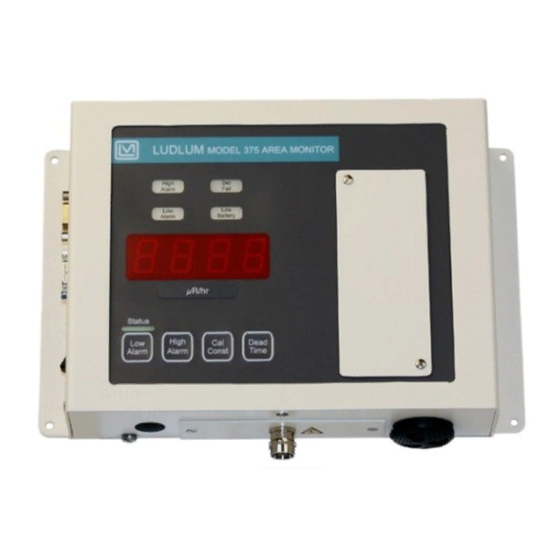
Model 375 Digital Wall-Mount Area Monitor is designed for visibility and ease of use. Featuring a wall-mount chassis, the Model 375 has a four-digit LED display that is readable from 9.1 m (30 ft) away. Backlit indicators warn of low-radiation alarm (yellow), high- radiation alarm (red), instrument failure (red), and low battery (yellow). -
Page 9: Getting Started
The Model 375 comes equipped with either an internal detector or a connector for use with an external detector. If your Model 375 is equipped with a connector on the bottom side of the chassis, an external detector is required. -
Page 10: Radiation Units
Radiation Units The Model 375 may be calibrated for almost any desired radiation units of measure. Common units of measure include mR/hr, µR/hr, R/hr, mSv/h, µSv/h, cps, cpm, and kcpm. In each case, the unit of measure is indicated underneath the four-digit display. -
Page 11: Model 375 Series One
The dead time correction is in units of microseconds*. The dead time correction can be set from 0.1 microseconds to 9999 micro- seconds*. : In the special case of the Model 375 Series One, Model 375 Series One make note of the following changes resulting from firmware modification:... -
Page 12: Operational Check
Models 375 (Including Series One), 375/1, 375/2 & 375/4 Section 2 Operational Check (optional) The operational check is an important assurance that the radiation detector and electronics are working correctly. Note: Ludlum Measurements suggests that an operational check be performed on a regular basis. Local procedures may supersede this suggestion. -
Page 13: Return For Repair And Calibration
Models 375 (Including Series One), 375/2, 375/4 & 375WT Technical Manual Return for Repair and Calibration To return an instrument for repair or calibration, provide sufficient packing material to prevent damage during shipment. Every returned instrument must be accompanied by an Instrument Return Form, which can be downloaded from the Ludlum website at www.ludlums.com. -
Page 14: Specifications
375/2 is from 1 µSv/h to 10 mSv/h (0.1 mR/hr to 1 R/hr). The operating range of the 375/4 is from 0.01 mSv/h to 100 mSv/h (1 mR/hr to 10 R/hr). External detectors will have different operating ranges. - Page 15 Models 375 (Including Series One), 375/1, 375/2 & 375/4 Section 3 DET Fail : indicated by a red light and an audible tone greater than 68 dB at 6.1 ft (2 m) for conditions of detector overload, no count from...
- Page 16 Models 375 (Including Series One), 375/1, 375/2 & 375/4 Section 3 Intensity can vary from approximately 68 dB to 100 dB through Audio: operation of the external rotary baffle and the internal voltage connection. Frequency is approximately 3 kHz. Power...
-
Page 17: Operator Controls And Setup
Models 375 (Including Series One), 375/1, 375/2 & 375/4 Section 4 Section Operator Controls and Setup Calibration Controls Remove the calibration cover to expose the calibration controls. Warning! Do not touch the circuit board in the calibration window due to potential for electric shock. -
Page 18: Dipswitch (Under Calibration Cover)
SINGLE BEEP output to a single half-second beep on LOW ALARM HIGH ALARM audio output (steady tone) is not limited. DET FAIL * See note on page 2-3 regarding Model 375 Series One. Ludlum Measurements, Inc. Page 4-2 May 2017... -
Page 19: Rs-232 Output
Models 375 (Including Series One), 375/1, 375/2 & 375/4 Section 4 RS-232 Output With the dipswitch in the left position, the Model 375 dumps RS- CAL MODE 232 data onto pin 4 of the 9-pin connector every two seconds. BYTE1... -
Page 20: 9-Pin Relays Connector
AlertNC pin9- AlarmNC Typical Internal Detector Setups Model 375/2 Typical response and set points for the model 375 with internal energy- compensated LND 71210 GM detector is as follows: Operating Voltage: 550 Vdc Threshold: 100 mVdc Calibration Constant: 1000 cpm/mR/hr Dead Time Correction: 30 µsec-150 µsec... - Page 21 Models 375 (Including Series One), 375/1, 375/2 & 375/4 Section 4 Model 375/4 Typical response and set points for the model 375 with internal energy- compensated LND 71412 GM detector is as follows: Operating Voltage: 550 Vdc Threshold: 100 mVdc Calibration Constant: 100 cpm/mR/hr Dead Time Correction: 30 µsec-150 µsec...
-
Page 22: Common Options And Modifications
Models 375 (Including Series One), 375/1, 375/2 & 375/4 Section 5 Section Common Options and Modifications Relay Options Internal Circuit-Board-Mounted Relays A 9-pin connector with male pins provides connection to three fail-safe form C relays, activiated by the LOW ALARM (alert), HIGH ALARM, and instrument FAIL. - Page 23 Allows the use of the 9-pin D female connector for RS-232 or remote use and does not interfere with the internal form C relays. This option includes a small enclosure connected to the Model 375 via a short cable, that accepts a standard mains power cord (conduit option is 4558-038-1).
- Page 24 Models 375 (Including Series One), 375/1, 375/2 & 375/4 Section 5 Figure 2. Mains Relay Box Front Panel. See below for description of noted parts in drawing above. A – conduit connector to the box if necessary. B – AC receptacle (removed if using conduit).
- Page 25 Models 375 (Including Series One), 375/1, 375/2 & 375/4 Section 5 Figure 3. Mains Relay Box Inside View. See below for description of noted parts in drawing above. A – 110/220 Vac conduit AC input. “H” = hot and “N” = neutral.
-
Page 26: Ethernet Interface Option
RS-232 port. The Model ALARM FAIL 375 will print once every 30 seconds as long as the alarm or fail condition is present. Setup You will need the following: a Model 375 instrument, a CBM-910 40- column printer, and a cable (8558-142). -
Page 27: Printer Dip Switch Settings
Models 375 (Including Series One), 375/1, 375/2 & 375/4 Section 5 RS-232 Data Format The data will be sent to the RS-232 port as: Byte 1 Byte 18 Space (20H) Byte 2 Byte 19 Byte 3 x OR x Byte 20... -
Page 28: Sigma Alarm Modification Option
60 seconds after the Model 375 is turned , in order to allow the Model 375 to accumulate a stable background radiation reading. Two other changes were made to the Model 375. The first change was to deactivate the indicator. Both the sigma-based alarm (set by the... -
Page 29: To 20 Ma Isolated Output Driver Option
4 to 20 mA Isolated Output Driver Option 4 to 20 mA Driver (Isolated) Modification Kit Part Number 4558-104 This circuit may be added to replace the Model 375 analog output, providing an isolated 4 to 20 mA output capability. The circuit board (LMI Part Number 5396-754) takes the analog output, varying between 0 and 5.00... - Page 30 Power Required maximum V = 15 V (connected internally) : 250 ohm Terminating Resistor Model 375 4 to 20 mA Isolated Output Connections (3-pin Hirose connector) Pin 1 is black (negative). Pin 2 is white (positive). Internal Board Header Pinout...
-
Page 31: Safety Considerations
Pollution Degree 2 (as defined by IEC 664) Cleaning Instructions and Precautions The Model 375 may be cleaned externally with bleach wipes or with a damp cloth, using water, Lysol or alcohol as a wetting agent. Do not immerse the instrument in any liquid. -
Page 32: Warning Markings And Symbols
Models 375 (Including Series One), 375/1, 375/2 & 375/4 Section 6 Warning Markings and Symbols Caution! The operator or responsible body is cautioned that the protection provided by the equipment may be impaired if the equipment is used in a manner not specified by Ludlum Measurements, Inc. -
Page 33: Electrical Safety Precautions
Models 375 (Including Series One), 375/1, 375/2 & 375/4 Section 6 Warning! The operator is strongly cautioned to take the following precautions to avoid contact with internal hazardous live parts that are accessible using a tool: 1. Turn the instrument power and disconnect the power cord. -
Page 34: Replacement Of Main Fuse
Models 375 (Including Series One), 375/1, 375/2 & 375/4 Section 6 result in the unit falling down and causing personal injury and/or property damage. Replacement of Main Fuse (Side Panel) Warning! For continued protection against risk of fire, replace only with fuse of the specified type and current rating. -
Page 35: Calibration
Models 375 (Including Series One), 375/1, 375/2 & 375/4 Section 7 Section Calibration High Voltage The high voltage is adjustable from 450-2500 Vdc using the potentiometer located under the calibration cover. The high voltage required will depend on the type of detector used. Internal GM detectors usually require 550 Vdc. -
Page 36: Analog Output
, located under the calibration cover, is used to set the backup battery trickle-charge voltage. This is typically set to 6.9 Vdc with the battery disconnected. * See note on page 2-3 regarding Model 375 Series One. Ludlum Measurements, Inc. Page 7-2... -
Page 37: Recycling
To this end, Ludlum Measurements, Inc. strives to supply the consumer of its goods with information regarding reuse and recycling of the many different types of materials used in its products. With many different agencies –... -
Page 38: Parts List
Models 375 (Including Series One), 375/1, 375/2 & 375/4 Section 9 Section Parts List Reference Description Part Number Model 375 Digital Wall- UNIT Completely Assembled 48-2230 Mount Area Monitor without Detector Model 375 Model 375/1 Digital Wall- UNIT Completely Assembled... - Page 39 Models 375 (Including Series One), 375/1, 375/2 & 375/4 Section 9 Reference Description Part Number C9-C11 100µF, 16V 04-5794 C12-C21 0.1µF, 500V 04-5696 C22-C23 0.01µF, 3kV 04-5762 C24-C33 0.1µF, 500V 04-5696 100pF, 100V 04-5743 10µF, 25V 04-5728 100pF, 100V 04-5743 100µF, 16V...
- Page 40 Models 375 (Including Series One), 375/1, 375/2 & 375/4 Section 9 Reference Description Part Number INTEGRATED MAX985EUK+T 06-6459 CIRCUITS LT1304CS8 06-6394 ICL7660SCBAZ 06-6437 TCM810LVNB713 06-6424 SA08-11EWA 07-6389 KB-2785YW 07-6371 KB-2685EW 07-6400 U111 ICM7218CIQI-LFT 06-6311 U131 SA08-11EWA 07-6389 U201 MAX220ESE+T 06-6329...
- Page 41 Models 375 (Including Series One), 375/1, 375/2 & 375/4 Section 9 DS11 KB-2550SGD 07-6370 SWITCHES S001 ALERT POINT 08-6728 S101 ALARM POINT 08-6728 S201 CALIBRATION CONSTANT 08-6728 S301 DEADTIME CORRECTION 08-6728 S501 DOWN 08-6728 S511 08-6728 S512 OPTION DIPSWITCH 08-6709...
- Page 42 Models 375 (Including Series One), 375/1, 375/2 & 375/4 Section 9 R253 82.5K, 1%, 250mW 12-7849 R331 1K, 1%, 250mW 12-7832 R332 165K, 1%, 250mW 12-7877 R341 2.2ohm, 5%, 250mW 12-7932 R431 1K, 1%, 250mW 12-7832 R421-R422 100K, 1%, 250mW...
-
Page 43: Wiring Diagram, Drawing 558 X 136
Models 375 (Including Series One), 375/1, 375/2 & 375/4 Section 9 Reference Description Part Number INDUCTORS 1Kohm 21-9008 L3-L4 2700ohm 21-9009 2700ohm 21-9009 1Kohm 21-9008 L411 220µHY 21-9678 RELAY RL1-RL3 G6K-2FY DC5 22-9332 TRANSFORMER 32377R 21-9925 MISCELLANEOUS SOCKET 44P PLCC... - Page 44 Models 375 (Including Series One), 375/1, 375/2 & 375/4 Section 10 Section Drawings Main Circuit Board, Drawing 558 x 1 (5 sheets) Main Circuit Board Component Layout Drawing 558 x 2 Main Circuit Board Component Layout Drawing 558 x 2A Wiring Diagram, Drawing 558 x 136 Ludlum Measurements, Inc.
Need help?
Do you have a question about the 375 and is the answer not in the manual?
Questions and answers