
Subscribe to Our Youtube Channel
Related Manuals for Axminster SX2.7


Summary of Contents for Axminster SX2.7
- Page 1 Code 107154 Original Instructions SX2.7 Mill Drill AT&M: 07/07/2020 BOOK VERSION: 2...
- Page 2 Cert No: SX2.7 EU Declaration of Conformity Axminster Tools & Machinery Ltd This machine complies with the following directives: Axminster Devon EX13 5PH UK axminster.co.uk 2006/42/EC EN 61000-3-2: 2014 2014/30/EU EN 61000-3-3:2013 declares that the machinery described:- EN 55014-1:2017 EN 55014-2: 2015...
-
Page 3: Important Safety Instruction
IMPORTANT SAFETY INSTRUCTION READ ALL INSTRUCTIONS AND WARNINGS BEFORE USING THIS TOOL Operator COMMON SENSE AND CAUTION ARE FACTORS WHICH CANNOT BE BUILT INTO ANY PRODUCT. THESE FACTORS MUST BE SUPPLIED BY THE OPERATOR. PLEASE REMEMBER: 1. When using electric tools, machines or equipment, basic safety precautions should always be followed to reduce the risk of fire, electric shock, and personal injury. -
Page 4: Grounding Instructions
IF THERE IS ANY QUESTION ABOUT A CONDITION BEING SAFE OR UNSAFE, DO NOT OPERATE THE TOOL! Grounding Instructions This machine has a three-prong plug, the third prong is the ground. Plug this cord only into a three-prong receptacle. Do not attempt to defeat the protection the ground wire provides by cutting off the round prong. - Page 5 Product selection instructions: The SX2.7 Bench mil drill have different models to choose for you, the standard model we call it name is SX2.7, you can add digital readout display the model name is SX2.7D ( you can see have a display in front of the head-stock)。...
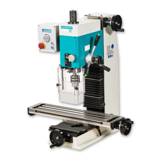
- Page 6 FEATURE / Model SX2.7 Y- axis handwheel Work tabel Column (with protect cover) Drill chuck with arbor Protective guard assembly Micro switch assembly Depth display (spindle travel) Screw for lock the spindle sleeve On/Off button Emergency stop switch Variable speed control knob...
-
Page 7: Installation
Installation CAUTION! DO NOT ATTEMPT TO USE THE MACHINE UNTIL INSTALLTION IS CAMPLETED, AND ALL PRELIMINARY CHECKS HAVE BEEN MADE IN ACCORDANCE WITH THIS MANUAL. MOUNTING THE MACHINE The machine should be mounted on a strong, heavy workbench, of sufficient height so that you do not need to bend your back to perform normal operations. -
Page 8: Operation
Operation 1. Before starts to use this machine, operator should go through the instructions carefully so as to acquaint with the construction of the machines, the functions of the various controls and also the driving systems. (1) Insert the power line insert the socket right of the fuselage, then power on;... - Page 9 Several characteristic functions 1. Spindle depth display 2. Chuck guard with safety switch 3. Spindle fine feeding ( tighten the lock knob “A” then turn the fine feeding knob “B”. 4. Two USB sockets, can supply power 5. Spindle speed readout 6.
- Page 10 4. Loosen the column lock handle, shake the lift handle and move the spindle box down; 5. Start the machine, select a good rotation speed, turn counterclockwise to turn the lifting handle, and drilling of milling can be done at this time; 6.
-
Page 11: After Using
After using After the completion of the work, the power supply should be cut off, the machine tool and environment should be cleaned well, and mechanical oil should be added to the exposed surface of the machine to prevent the surface of the machine from rusting and affecting the use and beauty of the machine. - Page 12 Common trouble problems and their Solutions Symptom Possible Cause Possible Solution Motor can not 1. The power supply is not on. 1. Turn on the emergency stop button start 2. Low voltage. 2. Check that the voltage of the power 3.
- Page 13 Parts drawing (I)
- Page 14 Parts list (I) drawing No. description Q'ty LXN3A02B01 Spindle box LXN3A02B02 Spindle box cover LXN3A02B03 Gear shaft LXN3A02B04 Worm shaft LXN3A02B05 Worm eccentric sleeve LXN3A02B07A Panel (standard) LXN3A02B07 Panel use for DRO LXN3A02B0700 Panel use for Mobile LX3C0212 MT3 Spindle LX3C02A01 R8 Spindle LX3C0213...
- Page 15 I-33 GB1096-79 4x8 Flat key 4*8 I-34 GB 894.1 - 20 Check ring 20 I-35 GB 879-86 - 3 x 8 Spring pin 3*8 I-36 LXN3A0218 Fine feed handwheel I-37 GB 77-85 - M6 x 6 Screw M6*6 I-38 GB1096-79 4x25 Flat key 4*25 I-39 GB 70-85 - M6 x 14...
-
Page 16: Parts Drawing
I-72 LX20206 B16 taper shank LX302A04 JT6 taper shank I-73 LX3C021100 Lifting bolt assembly I-74 GB 894.1 - 16 Check ring 16 I-75 LSX2.30201 Conductive ring assembly I-76 GB 818-85 - M3 x 4 Screw M3*4 I-77 LXN3B020700 Control handle assembly I-78 LXN3B020800 F/R control pole assembly... -
Page 17: Parts List
Parts list (2) Drawing No. Description Q'ty .2-1 LXN3A0901 Column .2-2 LXN3A0903A Metric rise and down leadscrew LXN3A0903B Inch rise and down leadscrew .2-3 LXN3A0908A Metric rise and down locking nut LXN3A0908B Inch rise and down locking nut .2-4 LXN3A0907A Metric rise and down leadscrew nut LXN3A0907B Inch rise and down leadscrew nut... - Page 18 Parts drawing (3) Parts list (3) Drawing No. Description Q'ty .3-1 LXN3A1101B Base .3-2 LXN3A11A03A Saddle .3-3 LXN3A11A02B Work table .3-4 LXN3A1108 leadscrew bearing seat .3-5 LXN3A11A04 Metric cross leadscrew LXN3A11A04A Inch cross leadscrew .3-6 LXN3A1106 Left end cover .3-7 LXN3A1107A Metric cross leadscrew nut LXN3A1107B...
- Page 19 .3-12 LXN3A11A01 Metric longitudinal leadscrew LXN3A11A01A Inch longitudinal leadscrew .3-13 LXN3A1112A Metric dial ring LXN3A1112B Inch dial ring .3-14 LX31142 Leadscrew clutch .3-15 GB 117-86 - A 4 x 28 Round taper pin 4*28 .3-16 GB827-86 2x4 Sign rive 2*4 .3-17 LX21118 Indicator...
- Page 20 Parts drawing (3A) Notice: this drawing is follow the SX2.7D Mill. The “D” means with “3 axis display”; use MG10V three axis magnetic grating ruler+Digital readout display. Parts list (3A) Drawing No. Description Q'ty .3A-1 LX2.31004 Washer .3A-2 LX21001A00 X axis magnetic ruler assembly .3A-3 GB 818-85 - M3 x 10 Screw M3*10...
-
Page 21: Specifications / Performance
Magnetic Grid Digital Display MG10V User Manual This is the optional function, only on “D” type had New features description Icon mode defines common function shortcuts (modify current value, repair&redirection, sensor adaptive mode) Fully aluminum alloy shell structure design, Ultra strong anti-interference ability. -
Page 22: Parameter Description
Tips: Please pay attention to the small icons on the buttons and understand the meaning of the icons, which will make the operation of the digital display faster and easier. Display Description Error Information description message Parameter input error Sensor failure: 1: sensor damage; 2: sensor cable is damaged; Magnetic stripe detection failed: 1: no magnetic strip;... - Page 23 Parts drawing (4) Parts list (4) Drawing No. Description Q'ty Drawing No. Description Q'ty .4-1 LX12304 Block .4-15 GB 819-85 - M4x10 Screw M4*10 GB 818-85 - M4 x .4-2 Screw M4*10 .4-16 LX3C23C05 Spacer bush .4-3 GB 97.1-85 - 4 Washer 4 .4-17 LX3C23C02...
- Page 24 Parts drawing (5) ----Standard Electrical type Parts list (5) Drawing No. Description Q'ty Drawing No. Description Q'ty .5-1 LXN3A1804 Lower cover .5-21 W80-750A /230V W80-750A Brushless motor .5-2 LXN3A1805 Upper cover plate .5-22 M12 draw lock .5-3 LXN3A18D0200 Rear hood assembly .5-23 QKS7 QKS7 Safety limit switch...
- Page 25 Parts drawing (5A) ----With “Display kit” Electrical type Parts list (5A) Drawing No. Description Q'ty Drawing No. Description Q'ty .5A-1 LXN3A1804 Lower cover .5A-23 MG10V MG10V Display .5A-2 LXN3A1805 Upper cover plate .5A-24 W80-750A W80-750A Brushless motor .5A-3 LXN3A180300 Rear hood assembly .5A-25 M12 draw lock .5A-4...
- Page 26 SX2.7 MILL Electrical wiring diagram Z750-1A/230V: PC Board M1: Brushless motor ZD-2: DC power supply plate FU: Fuse (8A/230V, 15A/110V) X-4D: Knob panel SB2: Tapping button XC: Socket with fuse Z: Filter (only use on 230V) SB1: Emergency stop switch...
- Page 27 SX2.7D MILL Electrical wiring diagram Z750-1A/230V: PC Board M1: Brushless motor ZD-2: DC power supply Fuse (8A/230V, plate 15A/110V) X-4D: Knob panel SB2: Tapping button Z: Filter (only use on 230V) XC: Socket with fuse SB1: Emergency stop switch Y-2: Liquid crystal board SQ: Micro switch SB3: Start/stop button L1: Magnet ring (only on...
-
Page 28: Packing List
Packing List Name Description Q'ty Remarks Bench Mill type: X2.7 or SX2.7 1 set Fuse 110V/20A or 230V/10A 1 pce. Manual manual 1 pce. Double end wrench S1*S2: 8*10、14*17、17*19 each 1 L hex wrench S: 3、4、5、6、8 each 1 U wrench assembly X3C004 1 pce. - Page 29 The Axminster guarantee is available on Craft, Trade, Engineer, Air Tools & CNC Technology Series machines Buy with confidence from Axminster! So sure are we of the quality, we cover all parts and labour free of charge for three years! axminstertools.com/3years...
Need help?
Do you have a question about the SX2.7 and is the answer not in the manual?
Questions and answers