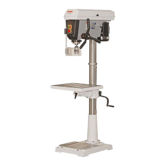
Axminster ATDP13B User Manual

Axminster ATDP13B User Manual

Pillar drills

Advertisement

ATDP13B
Code: 102552
Pillar Drills
User manual
ATDP16B
Code: 102553
ATDP17F
Code: 102554
ATDP13B Code 102552
ATDP16B Code 102553
ATDP17F Code 102554
ATDP20F Code 102555
ATDP20F
Code: 102555
AT&M: 12/09/2016
REF: 103253

Advertisement

Table of Contents
loading

Summary of Contents for Axminster ATDP13B

  • Page 1 ATDP13B Code 102552 ATDP16B Code 102553 ATDP17F Code 102554 ATDP20F Code 102555 Pillar Drills User manual ATDP13B Code: 102552 ATDP16B Code: 102553 ATDP17F Code: 102554 ATDP20F Code: 102555 AT&M: 12/09/2016 REF: 103253...
  • Page 2: Declaration Of Conformity

    Index of Contents Index of Contents Declaration of Conformity What’s Included 03-04 General Safety Instructions General Safety Instructions for Drilling Machines Specification Assembly 08-09-10-11-12-13 Illustration and Parts Description 14-15-16-17 Changing the Speed Levelling the Table (ATDP20F Only) Tilting the Table Removing the Keyless Chuck Maintenance Speed Select Tables...
  • Page 3: What's Included

    What’s included Model Number ZQJ4116K Model Number ZQJ4119K Quantity Item Part Quantity Item Part 1 No ATDP13B Small Bench Pillar Drill 1 No ATDP16B Medium Bench Pillar Drill Model Number ZQJ4125QK Model Number ZQJ4132K Quantity Item Part Quantity Item Part...
  • Page 4 What’s included...
  • Page 5: General Safety Instructions

    General Safety Instructions Work Place/Environment/Installation WARNING! UNDER NO CIRCUMSTANCES SHOULD CHILDREN BE ALLOWED IN WORK Mains Powered Machines/ Primary Precautions AREAS! These machines are supplied with a moulded 13 Amp. Plug and 3 core power cable. Before using the machine inspect the It is good practice to leave the machine unplugged until work cable and the plug to make sure that neither are damaged.
  • Page 6 General Safety Instructions for Drilling Machines 1. DO NOT operate the machine without carrying out 8. ALWAYS allow the drill to stop before removing drills or a preliminary inspection. swarf from around the job or the table. 2. CHECK that the speed is correct for the planned operation, 9.
  • Page 7: Specification

    Specification Code 102552 Code 102553 Model ATDP13B Model ATDP16B Power 550W (230V 1ph) Power 650W (230V 1ph) (12) 210-2,580rpm (12) 120-2,580rpm Speed Range Speed Range 165mm 178mm Throat Throat Taper Taper Chuck Cap/Type 16mm keyless Chuck Cap/Type 16mm keyless Chuck Travel...
  • Page 8 Having unpacked your machine and its accessories, please Fig 02 check the contents against the equipment list ”What’s Included” , if there are any discrepancies, please contact Axminster Tool Centre using the procedures laid down on our website. Retaining collar PLEASE DISPOSE OF THE PACKAGING RESPONSIBLY;...
  • Page 9 Assembly 3. Pick up the rise and fall gear rack, identify the top and the Fig 09 bottom, (the rack gearing is cut asymmetrically, with the gear cut extending closer to the bottom), make sure you have the rack the right way up, as it will allow you to drive the drill table up and down over its full range, see fig 06.
  • Page 10 Assembly 1. CHECK the drill head, ensure that the two hex socket grub Fig 13-14-15 screws that lock the head in place on the column are withdrawn and will not foul on the column when the head is fitted, see fig 17.
  • Page 11 Assembly Pulley Cover Knob 3. Locate the pulley cover knob (13), remove the Phillips screw, insert the screw through the pre-drilled hole in the pulley cover and secure the knob in place, see fig 27. Fig 27 Chuck guard 4. Locate the chuck guard assembly (7), chuck guard mounting bracket (6) and the four M6 button head Phillips screws (17).
  • Page 12 Assembly Fig30-31 Clamping screws Micro switch unit 8. Introduce the chuck guard rail (7) up through the centre of the micro switch and nip up the clamping knob to lock the chuck guard in place, see fig 32. Cutout slot NOTE: You can re-adjust the guard’s height for different drilling operations.
  • Page 13 Assembly 10. Open the pulley cover and check to see if the belt has been Fig 33-34-35 tensioned. If not, loosen the two motor yoke locks on either side of the drill head and move the tensioning lever back then re-tighten the motor yoke locks to lock the motor in place, see fig 36-37-38-39.
  • Page 14: Illustration And Parts Description

    Illustration and Parts Description 102552 ATDP13B 102553 ATDP16B 102554 ATDP17F 102555 ATDP20F...
  • Page 15 Illustration and Parts Description Pulley drive belt cover Pulley cover hand knob Chuck guard micro switch Motor yoke butterfly locking On/Off switch Emergency stop Button Motor Lever feed handle Retaining collar LED Light switch Keyless chuck Rise and fall rack Chuck guard Drill table Extension bracket arm...
  • Page 16 Illustration and Parts Description Drive belt tensioning lever lock Chuck guard micro switch Move the tensioning lever to release Opening the chuck guard or tension the drive belts whilst in operation will stop the drill insently. LED light (A) below the drill head pivots to Depth stop assembly (A), Depth stop scale (B) direct light down onto the work table and Depth stop adjustable nuts (C)
  • Page 17 Illustration and Parts Description On/Off switch (A) ATDP20F pillar drill control panel Motor yoke butterfly lock (A) Emergency stop button (B) NOTE: The LED light switch is above Drive belt tensioning lever lock (B) LED light switch (C) the On/Off switch assembly Lift and shift handle (A) for securing the table mounting arm Table tilt pointer (A) Clamping handle (B) for securing the table...
  • Page 18: Changing The Speed

    Changing the Speed WARNING! DISCONNECT THE PILLAR WARNING! TAKE CARE NOT TO TRAP YOUR DRILL FROM THE MAINS SUPPLY BEFORE FINGERS WHEN REPOSITIONING THE BELT CONTINUING! ON THE PULLEYS! 1. Open the pulley cover and loosen the motor yoke locks (A). 3.
  • Page 19: Tilting The Table

    Tilting the Table 1. The cust iron table can be tilted 45˚ degrees in both plains, Fig 46 to tilt the table you will need to first remove the tables 90˚ locking pin. To remove the locking pin use a 10mm spanner, turn the nut clockwise to draw the pin out.
  • Page 20: Maintenance

    IF THE POWER CABLE HAS BECOME DAMAGED. If any servicing (other than the above cleaning) becomes necessary, the unit should be returned to Axminster Tool Centre to be repaired by one of our qualified electricians. Contact our customer sales department for further assisance on 03332 406406 or email as @ csaxminster.co.uk .
  • Page 21: Speed Select Tables

    Speed Select Tables (12 Speed) 102552 ATDP13B Floor Pillar Drill (12 Speed) 102553 ATDP16B Bench Pillar Drill 102554 ATDP17F Floor Pillar Drill (12 Speed) 102553 ATDP20F Floor Pillar Drill...
  • Page 22: Drill Speed Material Table

    Drill Speed Material Table 12 Speed Spindle Jockey Pulley Motor Recommended Drill Size per Material Zinc Aluminium Cast Iron Steel Steel Cast Steel Average Guide Wood Plastic Diecast or Brass and Bronze Mild and Stanless and Speed Malleable Carbon Tool 50Hz inches inches...
  • Page 23: Troubleshooting

    Troubleshooting TROUBLE PROBABLE CAUSE REMEDY 1. Incorrect belt tension 1. Adjust the tension Noisy Operation 2. Dry spindle 2. Lubricate spindle 3. Loose spindle pulley 3. Checking tightness of retaining nut on pulley, and tighten if necessary 4. Loose motor pulley 4.
  • Page 24: Exploded Diagram/Parts List

    Exploded Diagram/Parts List...
  • Page 25 Exploded Diagram/Parts List PART DESCRIPTION BELT COVER BASE MOTOR COLUMN FLAT KEY RACK NUT M8 HEX SCREW WASHER 8 BOLT BOLT RIVET CAST BODY 0 SCALE IDLE PULLEY SHAFT GRIPPING SLEEVE CHECK RING LOCKING HANDLE BEARING WORM IDLE PULLEY SMALL SHAFT CHECK RING ROCKER BOLT...
  • Page 26 Exploded Diagram/Parts List DRIFT BEARING CONNECTING SHAFT BOLT CHECK RING CLAMP COVER MAIN SHAFT BOLT LIVE AXLE WASHER CHUCK SCREW WRENCH CIRCLIP THRUST BEARING BEARING BOLT M6X12 SPACER SLEEVE WASHER BEARING MICRO SWITCH SPINDLE HOUSING NUT M6 DRIVEN PULLEY SWITCH BOLT WASHER SHAFT SLEEVE...
  • Page 27 Exploded Diagram/Parts List...
  • Page 28: Wiring Diagram

    Wiring Diagram...
  • Page 29 CE Certificate...
  • Page 30 CE Certificate...
  • Page 31 CE Certificate...
  • Page 32 Normal wear and tear; misuse, abuse and neglect are excluded and the machine should not have engineering machines, Axminster Air compressors and Air Tools, and bench top grinders - no been modified in any way. Please do not attempt to service the product without first contacting us;...

This manual is also suitable for:

Atdp16bAtdp17fAtdp20f

Table of Contents