
Related Manuals for Axminster AW12BM


Summary of Contents for Axminster AW12BM
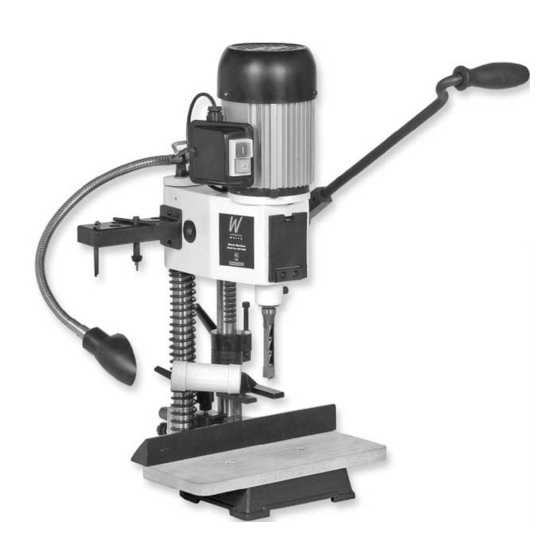
- Page 1 AW12BM 12mm Bench Morticer A X M I N S T E R W H I T E Axminster Reference No: AW12BM w w w. a x m i n s t e r. c o . u k...
-
Page 2: Table Of Contents
Index of Contents Page No. Index of Contents..............................2 Declaration of Conformity………….………..……..…………..............2 What’s in the Box………….………..……..…………..................3 Initial Actions............................4 General Instructions for 240v Machines..................4,5 Initial Assembly..........................5,6 Specifications….………..……..………….....................6 Machine Illustration of the 12mm Bench Morticer................7 Parts Identification and Description....................8 Machine Illustration of the 12mm Bench Morticer (continued)............9 Parts Identification and Description (Continued)................ -
Page 3: What's In The Box
What’s in the Box? Quantity Item Model Number 1 No. Mortising Machine Base with Mounting Columns, Plunge Depth Stops, Balance Spring, Head Box, Chisel Adaptor, Chuck and Fence Mounting Block assembled MS3612 1 No. 12mm Auger Chisel and Bit Set 1 No. -
Page 4: Initial Actions
Having unpacked your machine and its accessories, please check the contents against the equipment list ”What’s in the box”, if there are any discrepancies, please contact Axminster Power Tool Centre using the procedures laid down in the catalogue. Please dispose of the packaging responsibly;... -
Page 5: General Instructions For 240V Machines
General Instructions for 240v Machines (Continued) Keep the work area as well lit and uncluttered as is practical, this includes personnel as well as material. Under no circumstances should CHILDREN be allowed in work areas. It is good practice to leave the machine unplugged until work is about to commence, also make sure to unplug the machine when it is not in use, or unattended. -
Page 6: Initial Assembly
The pipe is located onto the hold down yoke using the bolt into a pre-threaded hole in the top of the left arm of the hold down yoke. Specifications Axminster No. (100081) AW12BM Rating: Light Trade Motor: 240V a.c. 50 Hz 370W... -
Page 7: Machine Illustration Of The 12Mm Bench Morticer
Machine Illustration of the 12mm Bench Morticer Large head machine screw Fig 1 Rise and fall Mechanism Motor Fig 1a Plunge lever Chuck assembly access door Depth stop bolt Lamp Dust extraction tube Lock nut Chisel clamping bolt Backfence Fig 1c Chisel mounting flange Base casting Mortising table... -
Page 8: Parts Identification And Description
Parts Identification and Description Please take some time to identify the various parts of your machine so that you are familiar with the terminology we will use to enable you to set up and operate your morticer safely and correctly. Base Casting This is the ‘Stand’... -
Page 9: Machine Illustration Of The 12Mm Bench Morticer (Continued)
Machine Illustration of the 12mm Bench Morticer (continued) Tool post column bridge Motor Fig 2a Castellated dog Light assembly Fig 2b Tool post column Double depth stop Shift lever handle Chisel Locking handle Backfence mounting block Counterbalance spring Grubscrew Fig 2 Fig 2c Scale Metal plate... -
Page 10: Parts Identification And Description (Continued)
Parts Identification and Description (Continued) Tool post Two steel shafts mounted into the rear of the base casting, they are the columns ‘runners’ for the headbox. They are ‘bridged’ at the top to increase accuracy (See fig 2) and rigidity, The machine lamp is mounted on the bridging lozenge. The right hand column has a rack cut in the surface which engages with a pinion in the headbox assembly to provide the rise and fall action. -
Page 11: Machine Illustration Of The 12Mm Bench Morticer (Continued)
Machine Illustration of the 12mm Bench Morticer (continued) NVR on/off switch assembly Fig 3a Motor Grip Sleeve Handle Headbox casting Chuck door removed for clarity Fig 3b Fig 3 Auger mounting chuck Backfence mounting block Spring Fig 3c... -
Page 12: Parts Identification And Description (Continued)
Parts Identification and Description (Continued) Hold Down Yoke This is a small ‘U’ shaped yoke casting. The underside of the arms of the ‘U’ (See fig 4b) are flat, to rest on the workpiece. In the middle of the yoke is a land sufficiently large enough to be bored through to accept the mounting rod. -
Page 13: Machine Illustration Of The 12Mm Bench Morticer (Continued)
Machine Illustration of the 12mm Bench Morticer (continued) Morticer converted to a drill press Drill press assembly Chisel mounting Fig 5 clamp bolt Fig 5c Fig 5a Chuck guard B6 to parallel chuck mounting shaft 1-13mm/B6 drill chuck Chuck mounting Fig 5b shaft Chuck key... -
Page 14: Setting Up The Machine
Setting up the Machine Overview Unlike the traditional morticing machines, which allow the table to move in 2 axis, i.e. side to side and front to rear, the table of this morticer does not move at all. The workpiece must be moved to achieve the side to side movement, and the placement of the back fence simulates the front to rear movement. - Page 15 Setting up the Machine (Continued) General Notes The morticer will generate a lot of ‘grip’ on the chisel, especially the first cut, or if the timber is a little green. Make sure you use the hold down yoke to help control the timber during the raise operation of the morticer.
-
Page 16: General Precautions Whilst Using A Drilling Machine
Reposition the plunge lever handle to give the most comfortable position and purchase on the lever, over the full distance of the movement you have just set. Using the AW12BM as a Drill Press Warning. Do not work on metal/material that could leave greasy/oily marks, without removing the mortising table. -
Page 17: Maintenance
Blow/suck the motor to remove any debris that might have lodged in the fan cover. Oil the chuck and exercise it over its full range to ensure the oil coats all moving parts. There are full ranges of mortice chisels and a useful sharpening set listed in Section 1 of the Axminster catalogue. -
Page 18: Illustrated Parts Beakdown For The 12Mm Bench Morticer
Illustrated Parts Beakdown for the 12mm Bench Morticer... -
Page 19: Illustrated Parts List For The 12Mm Bench Morticer
Illustrated Parts list for the 12mm Bench Morticer Description Unit Description Unit Motor Handle assembly Power cord Bolt Chuck Cap screw M8 x 10 Guide Head Bracket Label Lock washer Hex head bolt M8 x 20 Hex head bolt M8 x 15 Bushing Table Guide sleeve... - Page 20 Axminster Reference No: AW12BM A X M I N S T E R W H I T E Axminster Devon EX13 5PH UK FREEPHONE 0800 371822 www.axminster.co.uk...
Need help?
Do you have a question about the AW12BM and is the answer not in the manual?
Questions and answers