Sign In
Upload
Download
Table of Contents
Contents
Add to my manuals
Delete from my manuals
Share
URL of this page:
HTML Link:
Bookmark this page
Add
Manual will be automatically added to "My Manuals"
Print this page
×
Bookmark added
×
Added to my manuals
Manuals
Brands
Axminster Manuals
Drill
AP340PD
User manual
Axminster AP340PD User Manual
Pillar
Hide thumbs
1
2
3
4
5
6
7
8
9
10
11
12
13
14
15
16
17
18
19
20
21
22
23
24
25
26
27
28
29
30
31
32
Table Of Contents
33
page
of
33
Go
/
33
Contents
Table of Contents
Troubleshooting
Bookmarks
Table of Contents
Eu Declaration of Conformity
What's Included
General Safety Instructions
Specification
Illustration and Parts Description
Changing the Speed
Tilting the Table
Removing the Keyless Chuck
Maintenance
Speed Select Tables
Drill Speed Material Table
Troubleshooting
Exploded Diagram/Parts List
Wiring Diagram
Advertisement
Quick Links
Download this manual
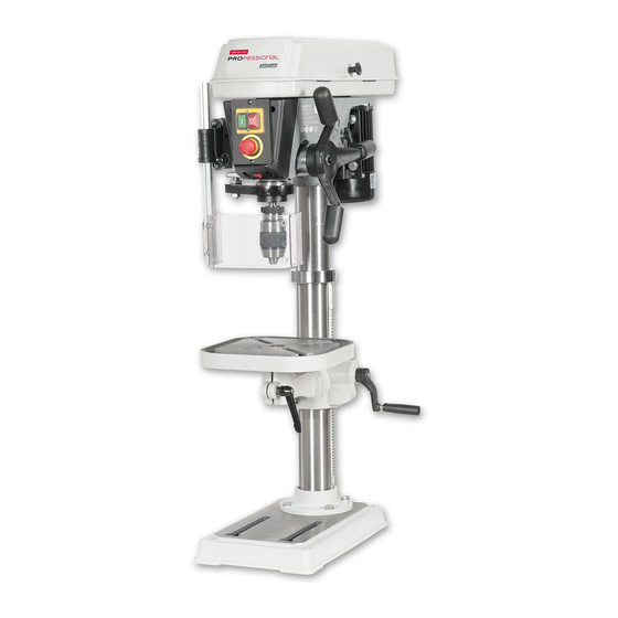
Pillar Drills
User manual
AP340PD
Code: 107704
AP325PD
Code: 107705
AP700PD
Code: 107706
AP340PD Code 107704
AP325PD Code 107705
AP700PD Code 107706
AP540PD Code 107707
AP540PD
Code: 107707
BOOK VERSION: 7
AT: 29/06/2022
Table of
Contents
Previous
Page
Next
Page
1
2
3
4
5
Advertisement
Table of Contents
Need help?
Do you have a question about the AP340PD and is the answer not in the manual?
Ask a question
Questions and answers
Related Manuals for Axminster AP340PD
Drill Axminster AW16BMST User Manual
Bench morticer (20 pages)
Drill Axminster AW12BM User Manual
12mm bench morticer (20 pages)
Drill Axminster Trade AT2001DP User Manual
Pillar drills (33 pages)
Drill Axminster AHDP13B User Manual
Pillar drills (40 pages)
Drill Axminster ATDP13B User Manual
Pillar drills (33 pages)
Drill Axminster ATDP16B User Manual
Pillar drills (33 pages)
Drill Axminster AC285PD User Manual
Pillar drills (36 pages)
Drill Axminster AC220RD User Manual
Pillar drills (36 pages)
Drill Axminster AP325PD User Manual
Pillar (33 pages)
Drill Axminster AP20BD User Manual
Bench & floor drills (32 pages)
Drill Axminster D.R.O. Micro Drill User Manual
(16 pages)
Drill Axminster Pillar Drills User Manual
Pillar drills (33 pages)
Drill Axminster SX2.7 Original Instructions Manual
Mill drill (30 pages)
Drill Axminster ZX25M User Manual
Vertical mill & drill (28 pages)
Drill Axminster Engineer Series Original Instructions Manual
Pillar drill (16 pages)
Drill Axminster Engineer Series Original Instructions Manual
Floor pillar drill (19 pages)
This manual is also suitable for:
Ap325pd
Ap700pd
Ap540pd
107704
107705
107706
...
Show all
107707
Table of Contents
Print
Rename the bookmark
Delete bookmark?
Delete from my manuals?
Login
Sign In
OR
Sign in with Facebook
Sign in with Google
Upload manual
Upload from disk
Upload from URL


Need help?
Do you have a question about the AP340PD and is the answer not in the manual?
Questions and answers