
Subscribe to Our Youtube Channel
Related Manuals for A&D SW Series


Summary of Contents for A&D SW Series
- Page 1 SW-6KS / SW-15KS SW-15KM / SW-30KM / SW-60KM / SW-150KM SW-60KL / SW-150KL 1WMPD4002080B...
- Page 2 Warning Definition The warning described in this manual has the following meaning: An imminently hazardous situation which, if not avoided, will result DANGER in death or serious injury. © 2011 A&D Company, Limited. All rights reserved. No part of this publication may be reproduced, transmitted, transcribed, or translated into any language in any form by any means without the written permission of A&D Company, Limited.
-
Page 3: Table Of Contents
CONTENTS 1. COMPLIANCE...................... 5 2. INTRODUCTION ....................6 3. FEATURES......................6 4. PRECAUTIONS....................7 4.1. Installing the scale ..................7 4.2. Operating the scale ................... 7 5. UNPACKING ......................8 6. DESCRIPTION OF EACH PART ................9 6.1. Display and symbols................10 6.2. - Page 4 13. FUNCTIONS ..................... 27 13.1. Setting the parameters ................27 13.2. Restoring the function settings to the factory set values......27 13.3. Function list ................... 28 14. OPTIONS ......................30 14.1. Using the HC-02i battery ............... 30 14.1.1. Installing the battery ..............30 14.1.2.
-
Page 5: Compliance
1. COMPLIANCE Compliance with FCC rules Please note that this equipment generates, uses and can radiate radio frequency energy. This equipment has been tested and has been found to comply with the limits of a Class A computing device pursuant to Subpart J of Part 15 of FCC rules. These rules are designed to provide reasonable protection against interference when equipment is operated in a commercial environment. -
Page 6: Introduction
2. INTRODUCTION This manual describes how the SW Series Super Washdown Scales work and how to get the most out of them in terms of performance. Please read this manual completely before using the scale. 3. FEATURES The SW Series Super Washdown Scales have the following features: ... -
Page 7: Precautions
4. PRECAUTIONS 4.1. Installing the scale DANGER • Ground the scale so that the user will not be subject to an electric shock. • The base frame is connected to the power GND (EXC-) inside the load cell. Be sure to earth ground the AC power cable. When the AC electrical outlet has no ground terminal, use the ground terminal (screw with the ground symbol) on the scale. -
Page 8: Unpacking
5. UNPACKING When unpacking, check whether all of the following items are included: Instruction manual SW series scale The scale components are different depending on the type of scale. With a display pole (no display stand) With a display stand (no display pole) -
Page 9: Description Of Each Part
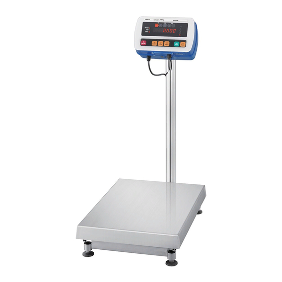
6. DESCRIPTION OF EACH PART Display Display pole AC power cable Spirit level Pole support foot Weighing pan Ground terminal (The above illustration is for scales with a display pole.) Leveling foot Display rear side Display knobs Display knobs Display stand (The above illustration is (The above illustration is for scales with a display pole.) -
Page 10: Display And Symbols
6.1. Display and symbols Display LED display STABLE indicator NET indicator Weighing STABLE units ZERO indicator ZERO ON/OFF key ON/OFF SAMPLE PRINT UNITS ZERO TARE SAMPLE key PRINT key ZERO key TARE key UNITS key Symbols Symbol Description ○ Turns on when the weight value is stable. STABLE Turns on when the NET weight is displayed. -
Page 11: Keys
6.2. Keys The keys are touch-sensitive. Three levels of key sensitivity are available and can be key 2 set in the function setting “ “. When set to “ “ (High), the keys can be operated with a gloved finger. ... - Page 12 When the tare is removed while the TARE operation is in progress and the ZERO operation described above is performed, the tare operation previously done is cleared and the NET indicator turns off. (Note: In some countries or areas, after the ZERO operation, the TARE operation will not be cleared without pressing the TARE key.)
-
Page 13: Setting Up
7. SETTING UP 7.1. Attaching the display pole to the base Lower part of SW-M / L series with a display pole the display pole 1. Remove the weighing pan from the base. 2. Remove the 4 screws from the lower part of the display pole. -
Page 14: Installing The Scale
7.2. Installing the scale 1. Select the place for installing the scale. Refer to “4. PRECAUTIONS”. 2. Adjust the level of the base, using the spirit level and leveling feet. Confirm that the bubble is in the center of the level. -
Page 15: Basic Operation
8. BASIC OPERATION 8.1. Turning the power ON and OFF 1. Press the ON/OFF key to turn the power ON. All the display symbols appear and the scale waits for the weight value to become stable. When the optional sealed lead acid (SLA) battery (HC-02i) is used: After all the display symbols appear, the battery capacity status is displayed for about 1.5 seconds as shown below. -
Page 16: Selecting A Weighing Unit
8.2. Selecting a weighing unit In the weighing mode, press the UNITS key to select a weighing unit. Each time the UNITS key is pressed, the unit changes as shown below. kg or g Ib-oz Ut-g Using the function setting “ ”, “kg”... -
Page 17: Weight Display Resolution
8.4. Weight display resolution The weight display resolution is a ratio of the minimum display to the weighing capacity. The SW series has three types of weight display resolution, as shown below. Normal: 1/3,000 High: 1/6,000 or 1/7,500 (depending on the weighing capacity) -
Page 18: Counting Mode
9. COUNTING MODE Determines a unit weight (the weight of one piece) from a known sample quantity, and calculates how many pieces are on the weighing pan using the unit weight. The unit weight is maintained even if the power is turned OFF. Press 1. -
Page 19: Comparator
10. COMPARATOR Five-level, three-level and seven-level (portion weighing mode) comparators are available. Each comparator mode compares the weight value against the preset limit values and outputs the results using LEDs (yellow / green / red). When the optional comparator relay output (SW-03) is installed, the results are output as a relay signal. -
Page 20: The Formula To Compare
10.1. The formula to compare Comparison is performed using the formula listed below and the results are output. Five-level comparator mode Results Comparison formula LED display Displayed value < LOLO limit value LOLO (Or over in the negative value) ( Red LED on) Displayed value <... -
Page 21: Entering The Comparator Values
10.2. Entering the comparator values 1. In the weighing mode, press and hold the SAMPLE key to enter the comparator value setting mode. 2. Enter the comparator values using the following keys. UNITS To shift the blinking digit to the right. PRINT To increase the value of the blinking digit by one. -
Page 22: Auto-Tare Function
11. AUTO-TARE FUNCTION The SW series has an auto-tare function to be used with the comparator mode enabled. Using this function in check weighing, the scale automatically tares, then displays “OK” for a certain amount of sample and repeats this process for the next weighing. -
Page 23: Calibration
12. CALIBRATION Adjusts the scale for accurate weighing. Calibrate the scale in the following cases. When the scale is first installed. When the scale has been moved. When the ambient environment has changed. For regular calibration. Note: Calibration can not be performed on the Legal for Trade models. -
Page 24: Gravity Acceleration Correction
Press the UNITS key to select an item press the TARE key to execute it. To exit from the calibration mode, press the ZERO1 key or the CAL switch. The scale returns to the weighing mode. 12.2. Gravity acceleration correction When the scale is first used or has been moved to another location, it should be calibrated using a calibration weight. -
Page 25: Calibration Using A Weight
12.3. Calibration using a weight Prepare a weight, preferably a weight with the same value as the weighing capacity of the scale to be calibrated. Note that the calibration weight value can be changed. 1. Turn the power ON and warm up the scale for at least half an hour. poff ... -
Page 26: Restoring The Factory Set Values
12.4. Restoring the factory set values If the gravity acceleration value or calibration weight value is changed unintentionally, restore those values to the factory set values, as follows. 1. Refer to “12.1. Calibration mode” to enter calibration mode. gravity acceleration value is displayed. Press twice 2. -
Page 27: Functions
13. FUNCTIONS The scale has function settings to specify the scale performance. The parameters set in the function settings are maintained even if the power is turned OFF. Parameter Item While holding down, press 13.1. Setting the parameters 1. Turn the power OFF. 2. -
Page 28: Function List
13.3. Function list Item Parameter Description 0 Auto power-off Auto power-off disabled Turns the power OFF function automatically Auto power-off enabled poff Weight display Normal (1/3,000) Changes the resolution 1 High (1/6,000 or 1/7,500) minimum display re5o Maximum (1/12,000 or 1/15,0 00) (See Note) ... - Page 29 Item Parameter Description Serial interface Only when the options, No reply except data to commands Response RS-232C or RS-422/485, 1 Reply to commands are used. 0 Comparator mode Five-level Cp-l Three-level Seven-level (portion weighing mode) 0 Comparison Comparator disabled conditions Compares all data...
-
Page 30: Options
14. OPTIONS 14.1. Using the HC-02i battery The scale can be operated with a sealed lead acid (SLA) battery, available as an option. The scale (with no other options) can be operated continuously for about 90 hours with a fully charged battery. ... -
Page 31: Charging The Battery
1. Disconnect the AC power cable from the electrical outlet. 2. Loosen the M4 screws and remove the rear cover of the display. Note: Take care not to drop the display. 3. Connect the wires inside the display to the battery with much care so that nothing touches the keys. -
Page 32: Rs-232C / Relay Output
14.2. SW-03 RS-232C / RELAY OUTPUT This interface allows the SW scale to be connected to an AD-8121 printer or a personal computer, and the relay outputs for comparator results are also available. When SW-03 is installed, the dust-tight and water-tight performance of the scale will be degraded. - Page 33 1. Disconnect the AC power cable from the electrical outlet. When the battery is installed, make sure that the scale is turned OFF. 2. Loosen the M4 screws and remove the rear cover of the display. Note: Take care not to drop the display. 3.
-
Page 34: Specifications
When connecting to an external device with hardware flow control, communication will be impossible using a cable without RTS and CTS connected. In that case, connect RTS and CTS. This will disable hardware flow control, but will enable communication. •... - Page 35 Circuit diagram 1 Receive data RXD 2 Transmit data TXD 3 Data set ready DSR 4 Signal ground SG 5 Shield SHLD SW is designed as DCE (Data Communication Equipment). LOLO 1 Relay output LOLO 2 Relay output LO 3 Relay output OK 4 Relay output HI 5 Relay output HIHI...
- Page 36 Data example Weighing data “kg” (+) + 0 0 1 2 3 4 5 _ k g Weighing data “g” (-) 0 0 0 0 1 2 3 4 _ _ g Counting data “pcs” (+) + 0 0 0 1 2 3 4 5 _ P C Out of weighing range (+) + 9 9 9 9 9 9 9 _ k g...
-
Page 37: Command Mode
14.2.3. Command mode In the command mode, the scale is controlled by commands that come from an external device such as a personal computer. Command List Command Description Remarks Send data immediately. Zero the scale when the weight is stable. Same as the ZERO key. - Page 38 Command Description Remarks When the five-level comparator mode is used: Not used When the three-level comparator mode is used: Not used When the seven-level comparator mode is used: Set the level 5 upper limit value. When the five-level comparator mode is used: Set the HIHI limit value.
- Page 39 Command examples (“_” indicates “Space” (20H).) aCk 1 The examples below are for the function setting “ “ (Reply to commands). Request the weight data. Command Reply + 0 0 1 2 3 4 5 _ k g C Stable positive data Unstable positive data + 0 0 0 7...
- Page 40 Five-level comparator mode…Send the current LO limit value. Three-level comparator mode…Not used Seven-level comparator mode…Send the current level 3 lower limit value. Command ? L 1 C Reply + 0 0 0 2 0 0 C Five-level comparator mode…Send the current LOLO limit value. Three-level comparator mode…Send the current LO limit value.
- Page 41 Five-level comparator mode…Set the LO limit value. Three-level comparator mode…Not used Seven-level comparator mode…Set the level 3 lower limit value. aCk 0 (No reply for the function setting “ “.) Send the six-digit value excluding the polarity and decimal point. Command + 0 0 0 2 0 0 C Reply...
-
Page 42: Rs-422 / 485
14.3. SW-04 RS-422 / 485 This interface allows a personal computer to connect and control up to 16 scales. When SW-04 is installed, the dust-tight and water-tight performance of the scale will be degraded. SW-04 unit includes an interface board, a connector cable (10 pins), two cable glands (for cable diameter 3.5 to 7.0 mm) and two screws (M3x8). -
Page 43: Specifications
The installation procedure is the same as for SW-03. Refer to “14.2.1. Installing SW- 03”. btpr Set the function settings “ ”, “ ”, “ ”, “ ”, “ ” and “ ” as necessary. Before using SW-04, the function setting “ ”... - Page 44 Example of connection RS-422 RS-485 Terminator (may be Terminator (may be built in the computer). built in the computer). Host computer Host computer Address 01 Address 01 Address 02 Address 02 Address 16 Address 16 Connect TRM to RDB at the farthest SW from the host computer.
- Page 45 Command examples (“_” indicates “Space” (20H).) aCk 1 The examples below are for the function setting “ “ (Reply to commands). The address ## = 23. Request a weight data. Command @ 2 3 Q C Reply @ 2 3 S T , + 0 0 1 2 3 4 5 _ k g C Stable data...
-
Page 46: Maintenance
15. MAINTENANCE 15.1. Notes on maintenance Do not disassemble the scale. Contact your local A&D dealer if the scale needs service or repair. Use the original packaging for transportation. Do not use organic solvents to clean the scale. Use a warm lint free cloth dampened with a mild detergent. - Page 47 Internal error Indicates that the mass sensor is malfunctioning. Indicates that the temperature sensor is malfunctioning. Indicates that the internal circuit is malfunctioning. Indicates that the memory (storage device) is malfunctioning. Indicates that the touch-sensitive switch is malfunctioning. Note: If the error persists or other errors occur, contact your local A&D dealer.
-
Page 48: Specifications
16. SPECIFICATIONS 16.1. Specifications MODEL SW-6KS SW-15KS SW-15KM SW-30KM Weighing capacity 0.002 0.005 0.005 0.01 Minimum display 0.001 * 0.002 * 0.002 * 0.005 * 0.0005 0.001 0.001 0.002 Weighing capacity 6000 15000 15000 30000 Minimum display Weighing capacity 0.005 0.01 0.01 0.02... - Page 49 MODEL SW-60KM SW-150KM SW-60KL SW-150KL Weighing capacity 0.02 0.05 0.02 0.05 Minimum display 0.01 * 0.02 * 0.01 * 0.02 * 0.005 0.01 0.005 0.01 Weighing capacity 0.05 0.05 Minimum display 0.02* 0.05* 0.02* 0.05* 0.01 0.02 0.01 0.02 Weighing capacity 2100 5200 2100...
-
Page 50: External Dimensions
16.2. External dimensions ●SW-6KS / SW-15KS (with a display pole) φ42.7 AC power cable ●SW-15KM / SW-30KM / SW-60KM / SW-150KM (with a display pole) AC power cable φ42.7 Unit: mm... - Page 51 ●SW-60KL / SW-150KL (with a display pole) AC power cable φ42.7 ●Display with a stand attached 135.9 φ 6- 5 Unit: mm...
-
Page 52: Gravity Acceleration Map
GRAVITY ACCELERATION MAP Values of gravity at various locations Amsterdam 9.813 m/s Manila 9.784 m/s Athens 9.807 m/s Melbourne 9.800 m/s Auckland NZ 9.799 m/s Mexico City 9.779 m/s Bangkok 9.783 m/s Milan 9.806 m/s Birmingham 9.813 m/s New York 9.802 m/s Brussels 9.811 m/s... - Page 53 World map...
- Page 54 MEMO...
- Page 56 3-23-14 Higashi-Ikebukuro, Toshima-ku, Tokyo 170-0013, JAPAN Telephone: [81] (3) 5391-6132 Fax: [81] (3) 5391-1566 A&D ENGINEERING, INC. 1756 Automation Parkway, San Jose, California 95131, U.S.A. Telephone: [1] (408) 263-5333 Fax: [1] (408)263-0119 A&D INSTRUMENTS LIMITED Unit 24/26 Blacklands Way, Abingdon Business Park, Abingdon, Oxfordshire OX14 1DY United Kingdom Telephone: [44] (1235) 550420 Fax: [44] (1235) 550485 A&D AUSTRALASIA PTY LTD...
Need help?
Do you have a question about the SW Series and is the answer not in the manual?
Questions and answers