Table of Contents
Advertisement
the benchmark for emc
M a n u a l
f o r
O p e r a t i o n
VDS 200Q series
Voltage Drop Simulator pulses 2b, 4
VDS 200Q25.2, VDS 200Q50.2, VDS 200Q100.2,
VDS 200Q150.2, VDS 200Q200.2
Testing of electronic modules in 12V/24V or 48V supply
systems.
The VDS 200Q is four-quadrant linear power amplifier with a
very low source impedance. It simulates the battery power
supply of a vehicle and complex power supply distortions in the
power range up to 12 kW. Many different waveforms are
integrated as standard such as pulse 2b required by ISO 7637
and the starting profile from ISO 16750 as well as requirements
from many manufacturers' standards like LV 124 and LV 148.
Version:
1.32.1 / 22.11.2019
Replaces:
1.3 / 18.11.2019
UserManual-VDS200Qxx.2-E-V1.3.1.doc
File Name:
Print Date:
22.11.2019
• ISO 7637
• ISO 16750
• SAE J1113
• Manufacturer spec
LV 124, LV 148, GM,
Ford, Chrysler, BMW,
VW, PSA, Renault,
Fiat ....
Advertisement
Table of Contents

Related Manuals for Ametek VDS 200Q Series


Summary of Contents for Ametek VDS 200Q Series
- Page 1 M a n u a l f o r O p e r a t i o n VDS 200Q series Voltage Drop Simulator pulses 2b, 4 VDS 200Q25.2, VDS 200Q50.2, VDS 200Q100.2, • ISO 7637 VDS 200Q150.2, VDS 200Q200.2 •...
- Page 2 4153 Reinach BL1 Switzerland Phone : +41 61 717 91 91 Fax : +41 61 717 91 99 URL : http://www.emtest.com Copyright © 2020 AMETEK CTS GmbH All right reserved. Specifications subject to change Manual for Operation V 1.3.1 2 / 36...
-
Page 3: Table Of Contents
Calibration and Verification ......................... 32 6.5.1. Factory calibration ............................32 6.5.2. Guideline to determine the calibration period of AMETEK CTS instrumentation ........32 6.5.3. Calibration of Accessories made by passive components only: ..............32 6.5.4. Periodic In-house verification ........................32 Delivery Groups ............................ -
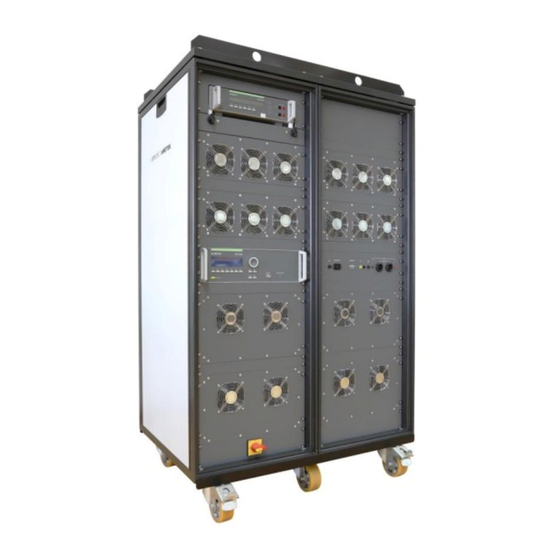
Page 4: Model Overview
AMETEK CTS VDS 200Q Series Model Overview 1.1. VDS 200Q Models Standard models Model voltage Voltage current Max. Inrush Sinus current f max VDS 200Q25.2 -20 to 80 V Imax = ±25 A 75A for 200 ms 250 kHz VDS 200Q50.2 -20 to 80 V Imax = ±50 A... -
Page 5: Operating Functions
AMETEK CTS VDS 200Q Series Operating Functions 2.1. Front view Display Function keys "F1..F7" BNC CRO Trigger ( for oscilloscope) "TEST ON" OUTPUT ACTIVE LED Knob (Inc/Dec) Cursor keys "" and "→" EXIT Display All functions and parameters are displayed (8 lines with max. 40 characters). - Page 6 AMETEK CTS VDS 200Q Series Additionally, on the front of the VDS 200Q models, there are the following elements: Power ON/OFF Switch Used to power on and off the system. At start, a synchronization and boot process will occur. After a few moments, the system is ready to be used.
- Page 7 AMETEK CTS VDS 200Q Series Output Connectors and Interconnects VDS 200Q100.2 5 Fuse 10 A (5x20 mm) against excess ground 1 Fuse 10 A (5x20 mm) for the PFM mains leakage current 2 Mains output to external PFM 200N100 6 DC out to DUT...
-
Page 8: Rear View Vds 200Q200.2
AMETEK CTS VDS 200Q Series 2.2. Rear view VDS 200Qxx.2 Emergency Switch 5-7 Optional AutoWave Out (N/C) 11 Ethernet (to AutoWave) Fuse or 8 AutoWave Out to VDS In 12 Framebus Out (additional Mains on some models) 9 VDS Analog In 13 IEEE 488.1... -
Page 9: Safety With Voltage Setting
These restrictions are explained within this paragraph. CAUTION: The VDS 200Q series, as well as most linear power amplifiers will create spikes at start and stop. These are limited to 15V normally, but inductive loads can generate high voltages. Do not touch any conducted parts of the system and be sure to remove the DUT during power up and shut down or damage may occur. - Page 10 AMETEK CTS VDS 200Q Series All these different test modes are changing generally the voltage supply setting of the generator in a different way. This would mean a certain risk for the operator to burn out the connected DUT by higher DC supply voltages as intended.
-
Page 11: Operation
Any waveform can be generated up to the upper bandwidth of the unit. F6 Source Settings Set-up, self-test, source settings and addresses of AMETEK CTS can be selected and displayed. Manual for Operation V 1.3.1... - Page 12 AMETEK CTS VDS 200Q Series F7 Service Set-up, self-test, source settings and addresses of AMETEK CTS can be selected and displayed. Manual for Operation V 1.3.1 12 / 36...
-
Page 13: Iso 7637
AMETEK CTS VDS 200Q Series 3.2.1. ISO 7637 3.2.1.1. Pulse 4 voltage drop This pulse simulates supply voltage reduction caused by energizing the starter-motor circuits of internal combustion engines, excluding spikes associated with starting. tf [Vb-Va1] < 5ms Limits depends VDS voltage range Input restrictions 0.0 V <= Vb + Va1 <= 30.0V (60.0V) -
Page 14: Iso 16750-2 Wd 03/2000-2
AMETEK CTS VDS 200Q Series 3.2.2. ISO 16750-2 WD 03/2000-2 3.2.2.1. Short voltage drop This test is to simulate the effect of a classical fuse actuation in another circuit. tr, tf = 10ms Limits depends VDS voltage range Input restrictions ... -
Page 15: Supply Voltage Profile
AMETEK CTS VDS 200Q Series 3.2.2.3. Supply voltage profile This test is to determine the reset behavior of the device under Test at different voltage drops. This test is applicable to equipment with reset function. Parameters: 0.0V 30.0V (60.0V) - 30.0V (- 60.0V) 30.0V... -
Page 16: Sinus Sweep
AMETEK CTS VDS 200Q Series 3.2.2.5. Sinus Sweep This test simulates a residual a.c. on the dc supply During Int f3 is applied. Limitations Vb + Vp <= 30.0V (60.0V ) Vb - Vp = 0.0V Parameters: 0.0V 30.0V (60.0V) 0.0V... -
Page 17: Functions
AMETEK CTS VDS 200Q Series 3.2.3. Functions 3.2.3.1. Sine wave Limitations Vb + Vp <= 30.0V (60.0V) Vb - Vp = 0.0V Parameters: 0.0V 30.0V (60.0V) 0.1V 0.1s 99.9s f< 100Hz 1.2Hz 0.001kHz 250.00kHz 1.0s 999.9s 30’000 / endl. -
Page 18: Jump Start
AMETEK CTS VDS 200Q Series 3.2.3.2. Jump Start Limitations V1 + V2 <= 30.0V (60.0V) = 0.0V V1 + V2 Parameters: 0.0V 30.0V (60.0V) - 30.0V (- 60.0V) 30.0V (60.0V) 0.01s 999.99s 0.01s 999.99s 0.01s 999.99s 0.1s 99.9s 30,000 / endl. -
Page 19: Pulse 4 ( Gm 9105 P)
AMETEK CTS VDS 200Q Series 3.2.3.4. Pulse 4 ( GM 9105 P) In addition to the ISO pulse 4 a 5Hz ripple of 1Vp-p is superimposed during t9 to Va. tr, tf = 10ms Input restrictions Vb + Va1 30.0V 0.0 V... -
Page 20: Service
Set-up The operator can change the simulator setting as explained on the next chapter. Source Settings The source settings menu contains features that are specific to the VDS 200Q series as explained in the next chapter. Manual for Operation V 1.3.1... -
Page 21: Setup
AMETEK CTS VDS 200Q Series 3.4. Setup This menu helps the user to define the configuration of the VDS 200. SETUP F1 : Change language F2 : LCD Backlighting F3 : Interfaces F4 : Keyboard-Beeper F5 : Power-on Counter F1 Change language The user can chose between two languages, German and English. -
Page 22: Source Settings
AMETEK CTS VDS 200Q Series 3.5. Source Settings The source settings menu contains features that are specific to the VDS 200Q series. SOURCE SETTINGS Vmax Pos = 80.0V Vmax neg = -20.0V Gain = 8x I peak = NO Peak... - Page 23 AMETEK CTS VDS 200Q Series Impedance The VDS 200Qxx.2 supports a selectable impedance from 10 mΩ to 200 mΩ or OFF (<10 mΩ according to ISO 7637-2) Vnom The battery setting that will be used, except in Source Mode. The current limit setting in amps. Voltage will be reduced in order to not exceed the current limit setting after a time selected by the I peak setting.
-
Page 24: Test Equipment
AMETEK CTS VDS 200Q Series Test Equipment 4.1. Construction The Voltage Drop Simulator VDS 200Q200.2 and VDS 200Q150.2 are built into two parallel 19" racks and is divided into several parts: the control unit, the power stage and the power supply. All other models are built into a single 19”... - Page 25 VDS 200Q Series As the VDS 200Q series is capable of negative voltages, care should be taken that the VDS 200Q is not used in the negative voltage range when a PFS 200N or LD 200N are connected. A setting is available to avoid overvoltage or undervoltage.
- Page 26 AMETEK CTS VDS 200Q Series 4.1.3. Ri settings The VDS 200Qxx.2 features a selectable Ri setting from 10 mΩ to 200 mΩ in 10 mΩ steps. “OFF” is also available for users who prefer to use the minimum source impedance available from the VDS 200Q (approx.
- Page 27 AMETEK CTS VDS 200Q Series I (A) 100% I 80% I U (V) Derating at Current in Extended Operating Mode NOTE: In default usage, this is carefully regulated current limit. When using the extended capabilities, the current limit is a hard hardware limitation and therefore, you may see more noise on the voltage signal when using the extended test envelope while in current limit.
-
Page 28: Technical Data
AMETEK CTS VDS 200Q Series Technical Data 5.1. Test level Voltage for VDS 200Q = to 80 V ± 2% ± 50 mV with 0.1 V steps setting approx. 50 mV at 0…80 V Output resolution Front panel setting Output resolution AutoWave setting AutoWave ADC 16 Bit: Resolution <... -
Page 29: General
AMETEK CTS VDS 200Q Series 5.5. General Dimensions Device in Rack Dimensions Weight H x W x D* VDS 200Q25.2 19” Rack 25 HU 132 x 55 x 80 cm 230 kg VDS 200Q50.2 19” Rack 25 HU 132 x 55 x 80 cm 275 kg VDS 200Q100.2... -
Page 30: Maintenance
AMETEK CTS VDS 200Q Series Maintenance 6.1. General The generator contains no user-serviceable parts inside. 6.2. Test set-up When setting up the test national and international regulations regarding human safety have to be guaranteed. The test setup must conform to the national and international regulations. -
Page 31: Example Test Setup With Autowave And Vds 200Q
AMETEK CTS VDS 200Q Series 6.4. Example Test setup with AutoWave and VDS 200Q Setup 13 example with: Rack AutoWave VDS 200Q200 Exernal: PFM 200N200 Manual for Operation V 1.3.1 31 / 36... -
Page 32: Calibration And Verification
Please refer to the corresponding standard before carrying out a calibration or verification. The standard describes the procedure, the tolerances and the necessary auxiliary means. Suitable calibration adapters are needed. To compare the verification results, AMETEK CTS suggests to refer to the wave shape and values of the original calibration certificate. -
Page 33: Delivery Groups
AMETEK CTS VDS 200Q Series Delivery Groups 7.1. Basic equipment VDS 200Qxx.2 VDS 200Q200.2 in double Rack (2 x 34HU) Three-phase mains connector (63 A) Emergency switch Connectors 200A (red/black, coded, 2 each) Ethernet cable 1 x Framebus cables 1 x Framebus terminator, No 101732 BNC Jumper Cable (0.15m) for CH1 to VDS 200Q150.1... -
Page 34: Appendix
AMETEK CTS VDS 200Q Series Appendix 8.1. Declaration of CE-Conformity 8.1.1. Declaration of CE-Conformity VDS 200Qxx.2 Manufacturer: AMETEK CTS GmbH Address: Sternenhofstr. 15 CH 4153 Reinach Switzerland declares, that under is sole responsibility, the product’s listed below, including all their options, are conformity with the applicable CE directives listed below using the relevant section of the following EC standards and other normative documents. -
Page 35: Connectors Vds 200Q200.2
AMETEK CTS VDS 200Q Series 8.1.1.1. Connectors General Live parts are on the plugging side touch protected in the unmated condition as per: IEC, EN 60529, DIN VDE 0470, part 1 IEC, EN 61010-2-031, VDE 0411, part 2-031 For additional connectors please download the catalogue from Multi Contact: www.multi-contact.com 8.1.2. -
Page 36: Vds 200Q Menu Overview
AMETEK CTS VDS 200Q Series 8.2. VDS 200Q Menu overview Manual for Operation V 1.3 36 / 36...
Need help?
Do you have a question about the VDS 200Q Series and is the answer not in the manual?
Questions and answers